


System Controls
SYS-APM001-EN Chiller System Design and Control 89
If the chiller and tower capabilities are conducive to this strategy, the location
and load profile determine if, when, and for how long the right conditions
might occur. Determine the optimum control sequence for the entire plant by
performing a detailed energy analysis of each component. Base the analysis
on realistic load profiles and ambient conditions, and account for the energy
used by all ancillary equipment.
For VPF systems, there will likely not be enough system flow to allow more
chillers than necessary to operate without requiring bypass to stay above the
chillers’ minimum flows.
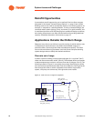
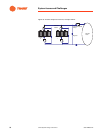
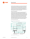
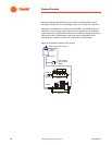
Condenser-Water System Control
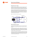
Minimum refrigerant pressure differential
Every chiller requires a certain refrigerant pressure differential between the
evaporator and condenser in order to operate. The chiller must develop its
pressure differential within a manufacturer-specified time or its controls will
shut it off. During some start-up conditions, this pressure differential may be
hard to produce within the time limitation.
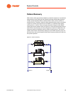
An example of such a condition is an office building that has been
unoccupied during a cool, clear, fall weekend. The tower sump water is at
40°F [4.4°C]. Monday is sunny and warm, which requires a chiller to be turned
on. Since the chiller is lightly loaded and the tower sump is large, the
pressure differential cannot be reached before the chiller turns off. If the
condenser flow rate for a given chiller can be reduced, this scenario is less
likely to occur. The lower flow rate increases the leaving condenser-water
temperature, which increases the condenser-refrigerant temperature and
refrigerant pressure.
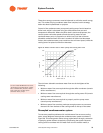
Table 17. VFDs and centrifugal chillers performance at 90% load
ECWT 2 Chillers* 1 Chiller Difference
85°F 306.4 268.0 -38.4
80°F 268.0 238.0 -30.0
75°F 230.8 210.6 -20.2
70°F 195.2 185.7 -9.5
65°F 160.3 164.3 +4.3
Note: Data shows only chiller power.
* Load equally divided.