


Chilled-Water System Variations
SYS-APM001-EN Chiller System Design and Control 77
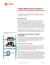
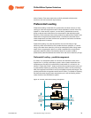
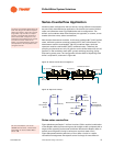
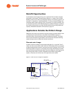
Series–Counterflow Application
Another system configuration that can be very energy efficient incorporates
the previously described series application, but does so for both the chilled
water and condenser water. Figure 48 shows such a configuration. The
chilled- and condenser-water flow directions are opposite, or counter, to one
another (thus the name, series-counterflow).
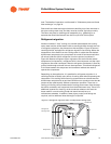
Note that the downstream machine, in this case, produces 40°F [4.4°C] chilled
water, while the upstream machine produces 50°F [10°C] chilled water. The
downstream machine receives 85°F [29.4°C] condenser water, while the
upstream machine receives 95°F [35°C] condenser water. Therefore, the
pumping requirements are only 1.2 gpm/ton on the chilled water side and 1.5
gpm/ton on the condenser water side—greatly reducing pumping, piping,
and cooling tower costs. The configuration has the effect of equalizing each
chiller’s required lift, as shown in Figure 49.
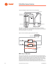
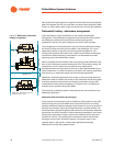
Figure 48. Series-counterflow arrangement
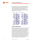
Figure 49. Equal lift concept
Series-series counterflow
Figure 48 shows two Duplex™ chillers in series. Chiller module (combination
of two Duplex chillers) power savings can be as high as 19% compared with a
single chiller operating at the same conditions. Because the Duplex chiller is
actually two refrigerant circuits in series on a common water circuit,
Figure 48 operates with the efficiency of four chiller circuits in a series-
counterflow arrangement. But system control is simply for two chillers in
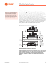
The series–counterflow configuration can
work with all types of chillers. Duplex™
chillers are shown in Figure 48. A single
large chiller may be built as a Duplex
machine, and would itself constitute a
series-counterflow arrangement. The
evaporator and condenser water circuits
are common to both halves of the
Duplex. Increased efficiency comes from
the separation of the compressors and
refrigerant circuits.
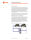
Upstream Chiller
Downstream Chiller
95°F [35°C]
105°F [40.6°C]
60°F [15.5°C]
85°F [29.4°C]
40°F [4.4°C]
50°F [10°C]
40°F
40°F
Series-
Single
Compressor
Chiller
95°F
105°F
Upstream Chiller
Downstream Chiller
105°F
65°F [36.1°C]
55°F [30.6°C]
55°F [30.6°C]
50°F
[40.6°C]
[40.6°C]
[10°C]
[4.4°C]
[35°C]
[4.4°C]
Arrangement
Counterflow
For more information, refer to the
ASHRAE Journal article, “Series-Series
Counterflow for Central Chilled Water
Plants.”
19