


System Design Options
SYS-APM001-EN Chiller System Design and Control 33
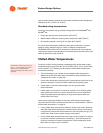
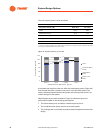
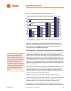
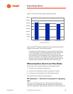
Figure 21. Chilled water system performance at part load
While the magnitude of the benefit of low-flow changes depends on the
chiller type used (centrifugal, absorption, helical-rotary, scroll), all chilled-
water systems can benefit from judicious use of reduced flow rates as
recommended by the ASHRAE GreenGuide
8
.
Coil response to decreased entering water temperature
A coil is a simple heat exchanger. To deliver the same sensible and latent
capacity when supplied with colder water, the coil’s controls respond by
reducing the flow rate of the water passing through it. Because the amount of
water decreases while the amount of heat exchanged remains constant, the
leaving water temperature increases. Thus, by supplying colder water to the
coils, a low-flow system can be applied to an existing building. In a retrofit
application, it is wise to reselect the coil, using the manufacturer’s selection
program, at a new chilled-water temperature to ensure its performance will
meet the requirements.
One possible concern of low supply-water temperatures is the ability of the
valve to control flow properly at low-load conditions. A properly-sized valve
with good range can work well in low-flow systems. In existing systems,
valves may need to be replaced if they cannot operate with the new range of
flows, but the coils do not need to be replaced.
Example of coil reselection at colder temperature/reduced flow rate
Water temperatures and flow rates are variables. They should be selected to
achieve an efficient and flexible water distribution system. Consider the
following example of a six-row coil in an existing air handling unit.
Table 9 shows an example of selecting a chilled-water cooling coil in a
13,000-cfm (6.1-m
3
/s) VAV air-handling unit. The left-hand column shows the
300
50
100
150
200
250
350
50
0
kW
50% Load Full Load75% Load25% Load
Base
Low Flow*
* Low-flow conditions in Figure 21 are 1.5 gpm/ton [0.027 L/s/kW] chilled water and 2.0 gpm/ton
[0.036 L/s/kW] condenser water.
If coil performance data is not available
from the original manufacturer, its
performance could be approximated
using current selection programs and
known details about the coil, such as fins
per foot, number of rows, tube diameter,
etc. Some designers use the following
approximation instead. For each 1.5 to
2.5°F [0.8°C to 1.4°C] the water
temperature entering the coil is reduced,
the coil returns the water 1°F [0.6°C]
warmer and gives approximately the
same sensible and total capacities. This
is a rough approximation and a coil’s
actual performance depends on its
design.