


74 Chiller System Design and Control SYS-APM001-EN
Chilled-Water System Variations
One caveat when applying this arrangement is that chillers on the production
side of the bypass line will run more often at low part-load conditions. Older
chillers or newer chillers with a high cycle point may not have this capability.
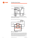
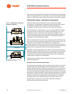
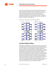
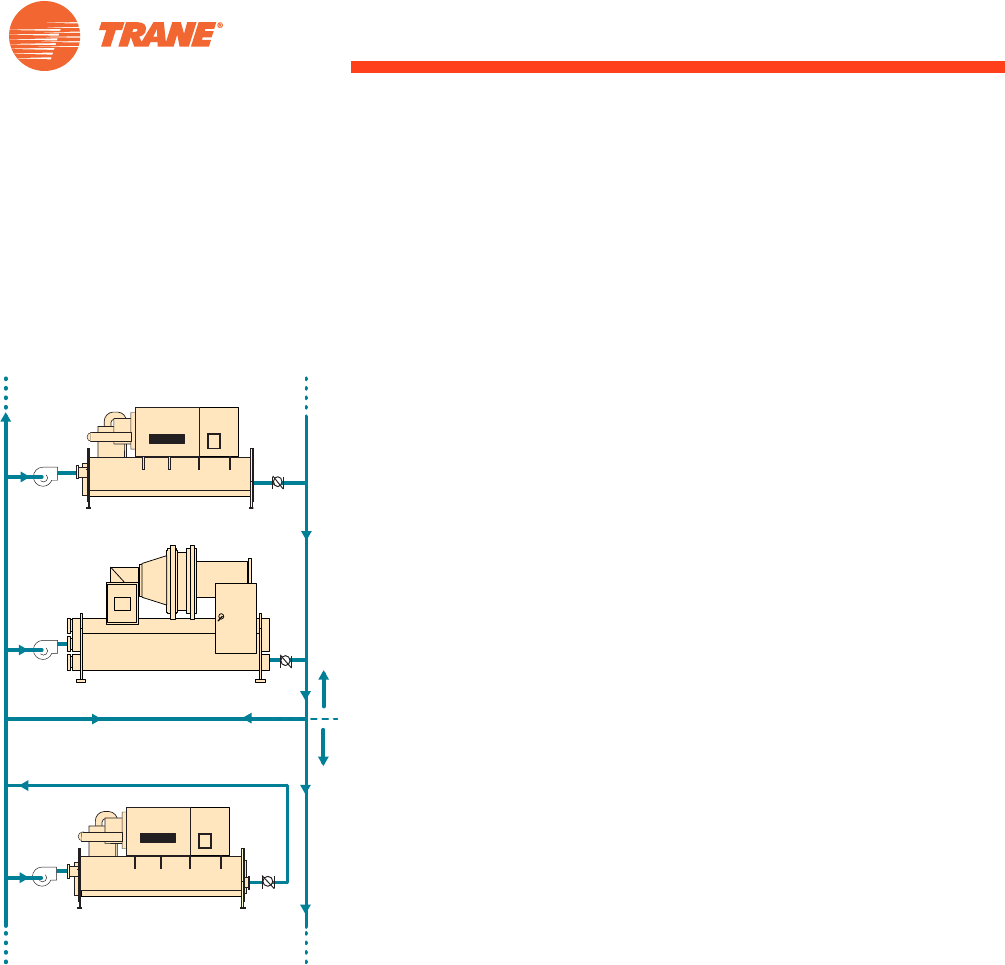
Preferential loading - sidestream arrangement
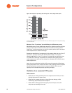
Figure 45 shows a simple modification to the traditional decoupled
arrangement. The sidestream arrangement ensures that the chiller piped in
the sidestream position still receives the warmest entering-water
temperature and can fully load it whenever the chiller plant operates.
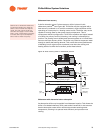
This arrangement is unique because it not only allows preferential loading,
but it also permits the cooling device (chiller, heat exchanger, etc.) in the
sidestream position to operate at any leaving-water temperature. This
configuration precools the system-return water for the chillers downstream,
reduces their loads and energy consumption, and decreases the overall
operating cost of the chilled-water system.
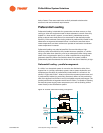
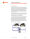
When cooling devices are located in the return piping of the distribution loop,
they do not contribute to system demands for flow. They simply reduce the
temperature of return water to the production loop. While this is
counterproductive to the principle of striving for the highest possible return
water temperature, it is often the best way to obtain free cooling, specialized
heat recovery, or reduce the capital cost of ice storage equipment.
Sidestream, decoupled applications are usually most economical when the
sidestream chiller is smaller than those on the production side of the bypass
line. Since pumping requirements and energy consumption change with
modifications to the system arrangement, it is best to use a computerized
analysis tool to model the economic effects.
The following are different system configurations that can benefit from the
sidestream application.
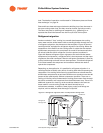
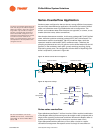
Sidestream plate-and-frame heat exchanger
A free-cooling heat exchanger may be capable of chilling water to only 48°F
[8.9°C] during some periods. Rather than overlook this portion of cooling
capacity assistance, the heat exchanger does whatever it can to its portion of
the total return stream. Figure 40 on page 70 shows a possible chilled- and
condenser-water piping arrangement that allows for simultaneous waterside
economizer and chiller operation. Chillers operating downstream can reduce
chilled-water temperature further, allowing simultaneous free cooling and
mechanical cooling. This configuration increases the hours that the heat
exchanger may be used. Since this capacity is brought to bear on the
warmest water in the system, it allows the highest heat exchanger
effectiveness and has the greatest impact.
Chiller 3
Production
Distribution
Chiller 2
Bypass Line
Chiller 1
Figure 45. Sidestream preferential
loading arrangement
Sidestream position receives the
warmest return water.