1
OVERVIEW
2
SYSTEM
CONFIGURATION
3
SPECIFICATIONS
4
SCREEN
CONFIGURATION
5
OPERATING
METHOD
6
FUNCTIONS
7
INTERNAL DEVICE
INTERFACE
FUNCTION
8
TROUBLESHOOTING
APPENDICES
2.5 Connection Cable
2.5.2 Connecting to serial communication module or computer link module
2 - 21
2.5.2 Connecting to serial communication module or computer link module
1 Connecting to serial communication module communicating with QCPU
(1) When using an RS-232 cable
The user is required to make a RS-232 cable for connecting GT SoftGOT1000 to a module.
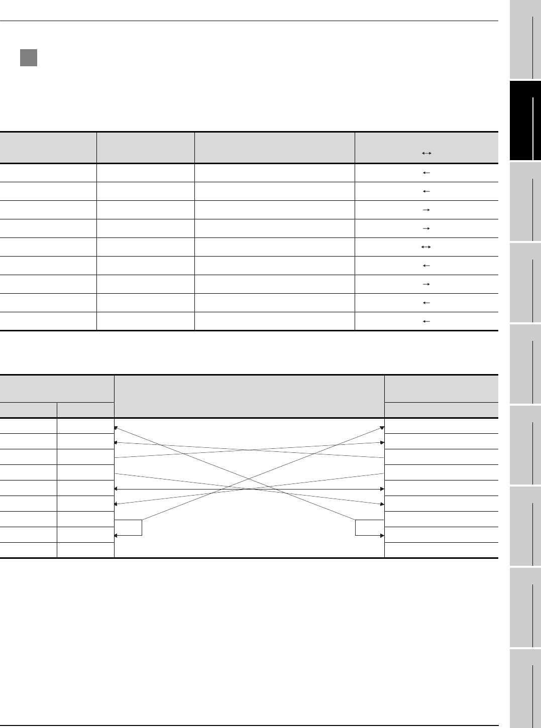
The cables connection diagram indicated below.
(a) Connector specifications
(b) Connection diagram
Pin No. Signal code Signal name
Signal direction
Q computible C24 GT SoftGOT1000
1 CD Receive carrier detection
2 RD(RXD) Receive data
3 SD(TXD) Send data
4 DTR(ER) Data terminal ready
5 SG Send ground
6 DSR(DR) Data set ready
7 RS(RTS) Request to send
8 CS(CTS) Clear to send
9 RI(CI) Call indication
1) Connection example which can turn ON/OFF CD signal (No. 1 pin)
Serial communication module
side
Cable Connection and Signal Direction
(Connection example for full duplex/half duplex communication)
GT SoftGOT1000
(Personal computer) side
Signal code Pin No. Signal code
CD 1 CD
RD(RXD) 2 RD(RXD)
SD(TXD) 3 SD(TXD)
DTR(ER) 4 DTR(ER)
SG 5 SG
DSR(DR) 6 DSR(DR)
RS(RTS) 7 RS(RTS)
CS(CTS) 8 CS(CTS)
R1(CI) 9


