


1
OVERVIEW
2
SYSTEM
CONFIGURATION
3
SPECIFICATIONS
4
SCREEN
CONFIGURATION
5
OPERATING
METHOD
6
FUNCTIONS
7
INTERNAL DEVICE
INTERFACE
FUNCTION
8
TROUBLESHOOTING
APPENDICES
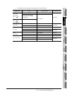
2.5 Connection Cable
2.5.2 Connecting to serial communication module or computer link module
2 - 23
2 Connecting to serial communication module or computer link module communicating
with QnACPU, ACPU, or motion controller CPU (A series)
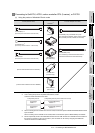
(1) When using an RS-232 cable
(a) Using the product of Mitsubishi Erectric make.
(b) When using an RS-232 cable prerared by user
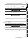
The cable connection diagrams are indicated below.
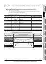
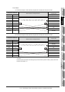
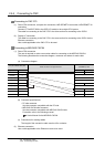
For QnA Series (large-scale QC24(N))
* DC code control or DTR/DSR control is enabled by connecting the QC24 (N) to an external device as shown
above.
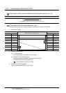
* DC code control or DTR/DSR control is enabled by connecting the QC24 (N) to an external device as shown
above.
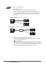
RS-232 cable
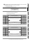
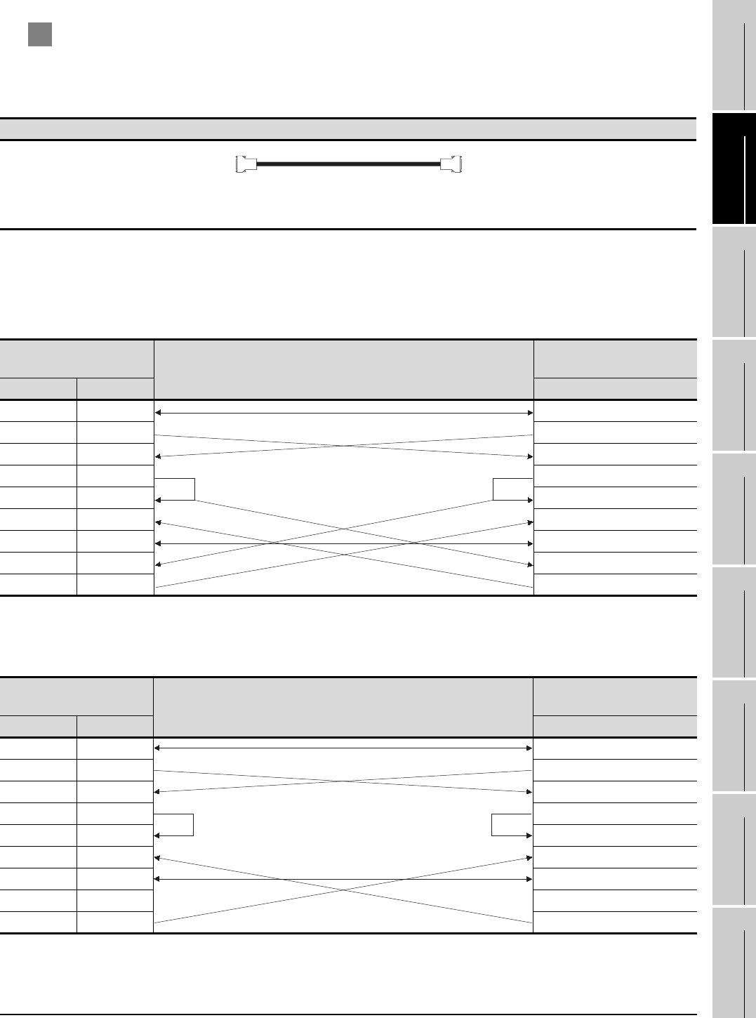
1) Example of connection to an external device that allows the CD signal (No.8 pin) to be turned ON/OFF
Serial communication
module side
Cable Connection and Signal Direction
(Connection example for full duplex/half duplex communication)
GT SoftGOT1000 (Personal
computer) side
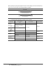
Signal code Pin No. Signal code
FG 1 FG
SD (TXD) 2 SD (TXD)
RD (RXD) 3 RD (RXD)
RS 4 RS
CS (CTS) 5 CS (CTS)
DSR (DR) 6 DSR (DR)
SG 7 SG
CD 8 CD
DTR (ER) 20 DTR (ER)
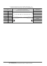
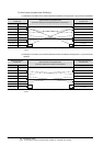
2) Example of connection to an external device that does not allow the CD signal (No. 8 pin) to be turned
ON/OFF
Serial communication
module side
Cable Connection and Signal Direction
(Connection example for full duplex communication)
GT SoftGOT1000 (Personal
computer) side
Signal code Pin No. Signal code
FG 1 FG
SD (TXD) 2 SD (TXD)
RD (RXD) 3 RD (RXD)
RS 4 RS
CS (CTS) 5 CS (CTS)
DSR (DR) 6 DSR (DR)
SG 7 SG
CD 8 CD
DTR (ER) 20 DTR (ER)
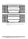
AC30N2A
(For personal computer side 25 pin D-sub connector