2 - 30
2.5 Connection Cable
2.5.7 Connecting to Omron PLC CPU
2.5.7 Connecting to Omron PLC CPU
1 When using a product made in Mitsubishi Electric System Service Co., Ltd.
2 When using an RS-232 cable prepared by user
The following describes the connection diagram, connector and others for each cable.
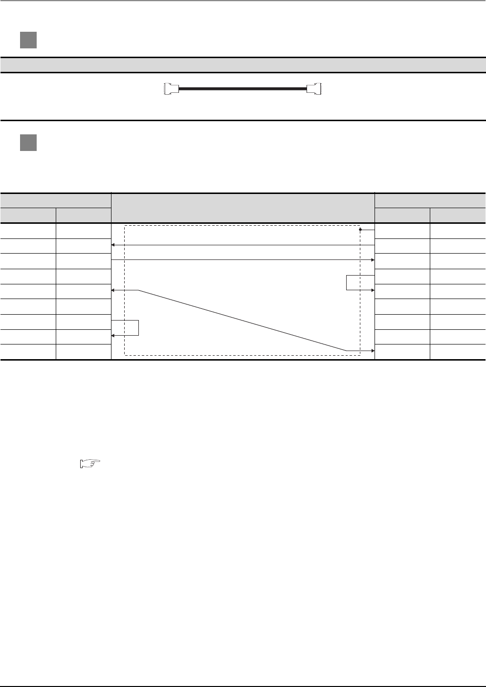
(1) Connection diagram
(2) Connector specifications
(a) PC side connector
Use the connector compatible with the PC side.
(b) Omron PLC CPU side connector
Use the connector compatible with Omron PLC CPU side.
For details, refer to the following manual.
User's Manual for Omron PLC CPU
(3) Precautions for creating cables
The length of the cable must be 15m or less.
RS-232 cable
PC (GT SoftGOT1000) side
Cable connection and signal direction
Omron products side
Signal name Pin No. Pin No. Signal name
CD 1 1FG
RD (RXD) 2 2SD
SD (TXD) 3 3RD
ER (DTR) 4 4RS
SG 5 5CS
DR (DSR) 6 6-
RS (RTS) 7 7FR
CS (CTS) 8 8ER
-9 9SG
GT09-C30R20101-9P(3m) (For the 9-pin D-sub connector of the PC


