


2 - 26
2.5 Connection Cable
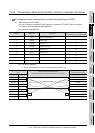
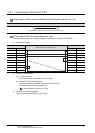
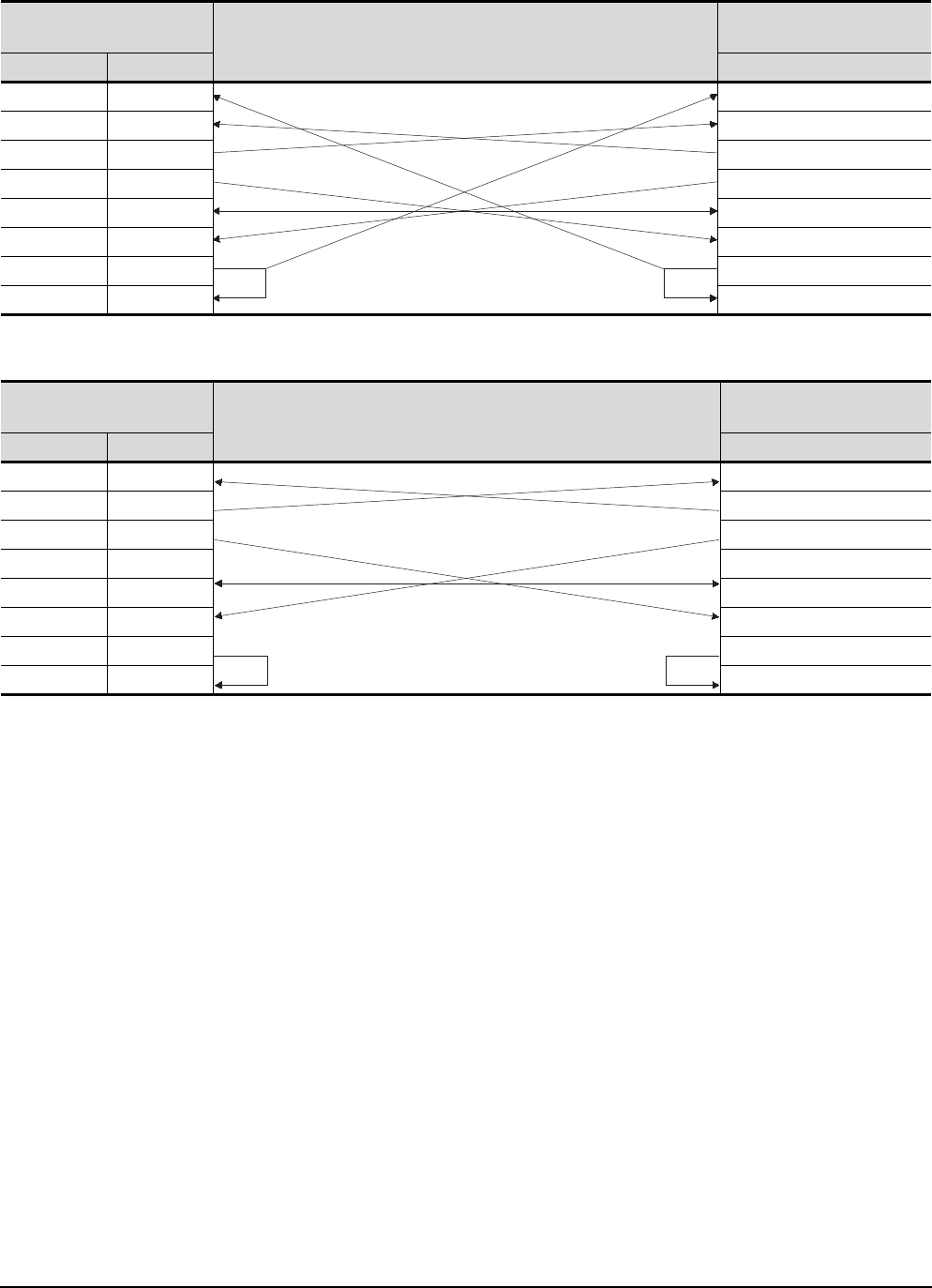
2.5.2 Connecting to serial communication module or computer link module
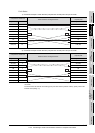
*1 DC code control or DTR/DSR control is enabled by connecting the DTR and DSR signals of the computer link
module to an external device as shown above.
*2 When performing a communication in the connection shown above, the CD signal is not required to be
connected.
For the RS-232C CD terminal check setting (set by the buffer memory address "10BH"), specify "without CD
terminal check (writing "1")".
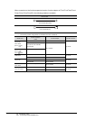
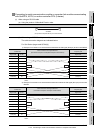
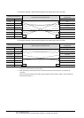
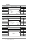
3) Connection example 1 when the C24 (computer link module) has a 9-pin connector
Computer link module side
Cable Connection and Signal Direction
GT SoftGOT1000 (Personal
computer) side
Signal code Pin No. Signal code
CD 1 CD
RD (RXD) 2 RD (RXD)
SD (TXD) 3 SD (TXD)
DTR (ER) 4 DTR (ER)
SG 5 SG
DSR (DR) 6 DSR (DR)
RS (RTS) 7 RS (RTS)
CS (CTS) 8 CS (CTS)
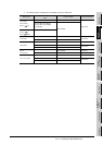
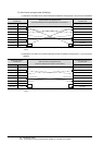
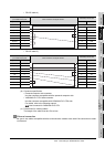
4) Connection example 2 when the C24 (computer link module) has a 9-pin connector
Computer link module side
Cable Connection and Signal Direction
GT SoftGOT1000 (Personal
computer) side
Signal code Pin No. Signal code
CD 1 CD
RD (RXD) 2 RD (RXD)
SD (TXD) 3 SD (TXD)
DTR (ER) 4 DTR (ER)
SG 5 SG
DSR (DR) 6 DSR (DR)
RS (RTS) 7 RS (RTS)
CS (CTS) 8 CS (CTS)