


5-10
Performance Tests
Test 5. Amplitude Accuracy and Linearity
completely filled in.
10 Disconnect the fiber-optic cable from the optical power meter and
connect it to the Agilent 86120C’s OPTICAL INPUT connector.
11 Set the optical attenuator for the value that you recorded in Step 8.
12 Place the polarization controller in the auto scan mode.
13 Press the Agilent 86120C’s front-panel Preset key.
14 Press List by Power, Appl’s, and then DRIFT.
15 After two minutes, stop the polarization controller’s auto scan function.
16 Press the MAX-MIN softkey so that MAX is highlighted. Enter the
maximum drift reading on the following line:
maximum drift: ____________
17 Press the MAX-MIN softkey so that MIN is highlighted. Enter the
minimum drift reading on the following line:
minimum drift: ____________
18 Use the values recorded in Step 8, Step 16, and Step 17 to calculate the
power-correction offset value as shown in the following equation:
Enter the calculate value on the following line:
power-correction offset: ____________
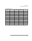
19 Change the attenuator to the settings shown in Table 5-21. For each
setting, record the power measured on the Agilent 86120C.
After completing this step, the table’s column titled “Agilent 86120C
Power Reading” should be completely filled in.
20 Calculate the “Linearity” value for each row in the table using the
following equation:
21 Compare the linearity values with the specification listed in Chapter 6,
“Specifications and Regulatory Information”. The data may show
multiple amplitude plateaus separated by small amplitude steps. This is
not a problem as long as the amplitude steps are within the linearity
specification.
offset
minimum drift maximum drift+
2
---------------------------------------------------------------------------
Pwr–=
Linearity Power Meter Reading 86120C Power Reading– offset–=