Programmer’s Guide, cont’d
MTPX Plus Twisted Pair Matrix Switchers • Programmer’s Guide
4-8
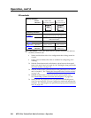
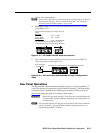
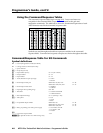
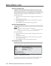
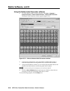
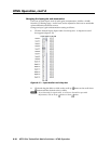
Using the Command/Response Tables
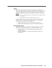
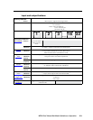
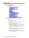
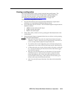
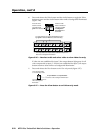
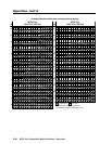
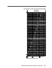
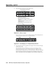
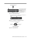
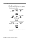
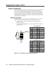
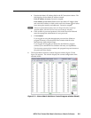
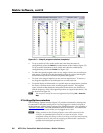
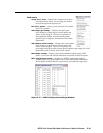
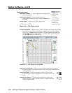
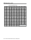
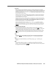
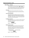
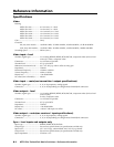
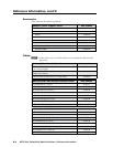
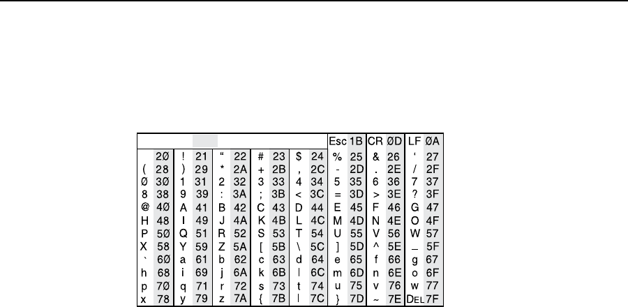
The command/response tables begin on page 4-10. Lower-case letters are
acceptable in the command field except where indicated for the gain and
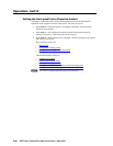
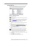
attenuation commands. The table below shows the hexadecimal equivalent of each
ASCII character used in the command/response table.
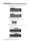
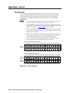
ASCII to HEX Conversion Table
Space
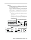
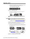
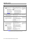
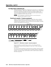
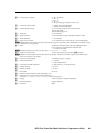
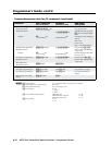
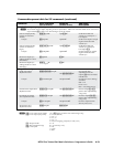
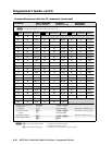
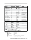
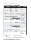
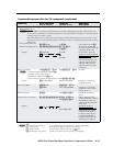
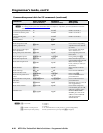
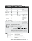
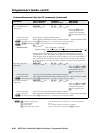
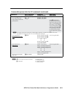
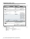
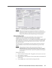
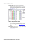
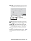
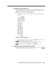
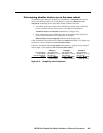
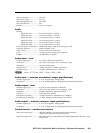
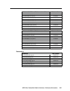
Symbols are used throughout the table to represent variables in the command/
response fields. Command and response examples are shown throughout the table.
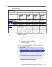
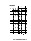
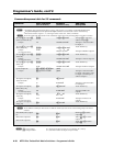
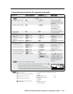
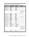
Command/Response Table for SIS Commands
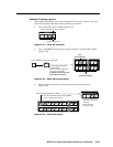
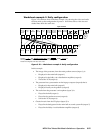
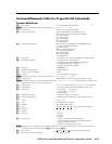
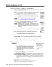
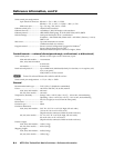
Symbol definitions
]
= CR/LF (carriage return/line feed, hex 0D 0A)
}
= Carriage return (no line feed, hex 0D))
• = Space character
E
= Escape key (hex 1B)
X!
= Input number (for tie)
00 – 32 (00 = untied)
X@
= Output number 01 – 32
X#
= Input number 01 – 32
X$
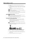
= Audio/RS-232 wire pair input type 0 = audio
1 = RS-232
X%
= RS-232outputinsertport MTPXPlus168,816,1616 01–08
MTPXPlus1632,3216,3232 01–16
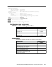
X^
= RS-232 output insert status 0 = disabled
1 = enabled
X&
= Input signal level/peaking range 000 – 255
X*
= Threshold 0 = outside of threshold
1 = within threshold
X(
= Skew adjustment range 00 – 31 (each step = 2ns)
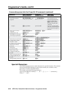
X1)
= Video plane 0 = red
1 = green
2 = blue
X1!
= Pre-peakableoutputnumber MTPXPlus168 01–04
MTPXPlus816,1616,3216 01–08
MTPXPlus1632,3232 01–16
X1@
= Mute, pre-peaking, Lock mode, power supply 0 = off/mode 0/not OK
1 = on/mode 1/OK
2 = mode 2
X1#
= Local video output number 1 or 2
N
X1#
isapplicabletomatrixsizes1632andlargeronly.