Installation, cont’d
MTPX Plus Twisted Pair Matrix Switchers • Installation
2-10
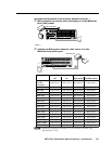
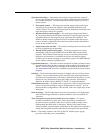
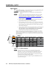
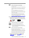
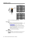
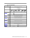
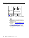
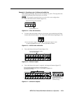
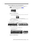
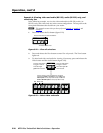
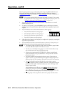
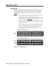
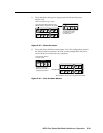
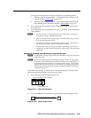
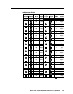
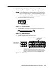
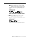
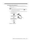
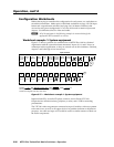
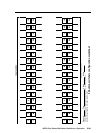
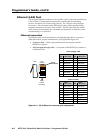
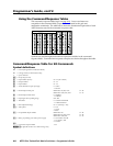
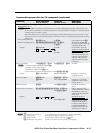
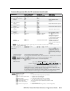
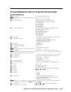
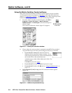
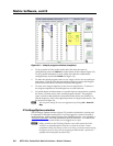
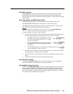
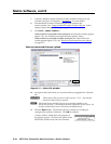
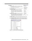
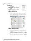
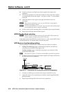
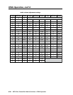
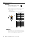
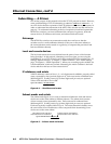
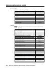
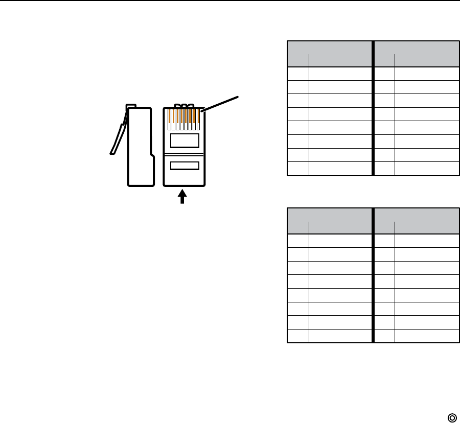
Patch (straight) cable
Side 1 Side 2
Pin Wire color Pin Wire color
1 White-orange 1 White-orange
2Orange 2Orange
3 White-green 3 White-green
4 Blue 4 Blue
5 White-blue 5 White-blue
6 Green 6 Green
7 White-brown 7 White-brown
8 Brown 8 Brown
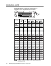
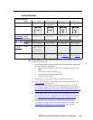
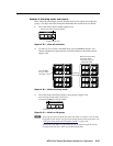
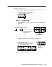
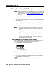
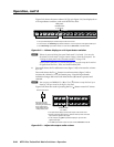
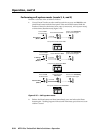
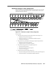
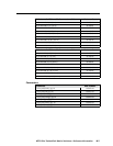
Crossover cable
Side 1 Side 2
Pin Wire color Pin Wire color
1 White-orange 1 White-green
2Orange 2 Green
3 White-green 3 White-orange
4 Blue 4 Blue
5 White-blue 5 White-blue
6 Green 6Orange
7 White-brown 7 White-brown
8 Brown 8 Brown
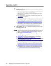
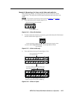
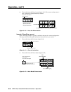
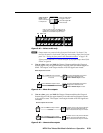
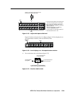
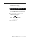
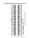
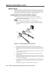
Side
12345678
Insert
Twisted
Pair Wires
Pins:
RJ-45
Connector
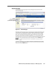
Figure 2-10 — RJ-45 connector and pinout tables
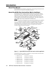
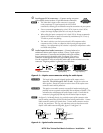
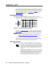
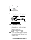
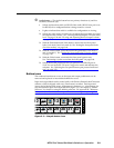
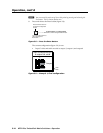
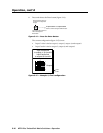
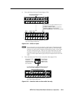
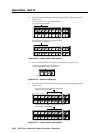
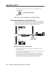
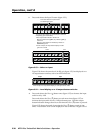
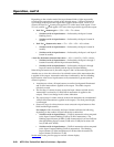
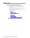
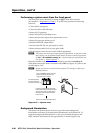
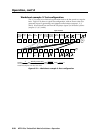
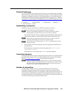
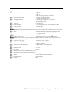
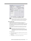
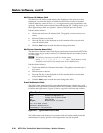
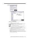
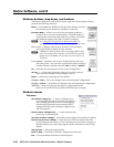
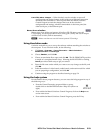
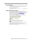
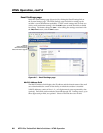
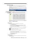
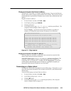
Reset button
k
Reset button — The Reset button initiates two levels of reset to the
matrix switcher. For two different reset levels, press and hold the button
while the switcher is running or while you power up the switcher.
See “Rear Panel Operations” in chapter 3, “Operation”, for details.
• Rear panel (mode 5) system reset — Press and hold the Reset button
until the Reset LED blinks three times (approximately 9 seconds), then
release the button and push it again. This reset clears all ties and presets
and resets all audio gains to 0 dB.
• Hard reset — Press and hold the Reset button while powering up the
switcher to perform all of the mode 5 reset functions and restore the
switcher to the default factory conditions.
N
Hardresetdoesnotclearthecurrentconguration.
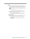
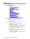
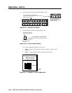
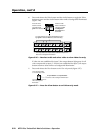
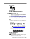
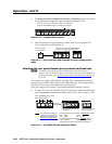
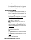
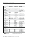
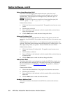
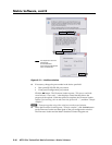
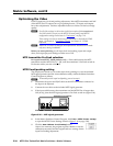
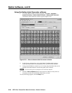
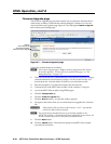
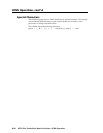
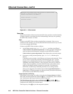
Power connection
l
AC power connector — Plug a standard IEC power cord into this connector to
connecttheswitchertoa100VACto240VAC,50or60Hzpowersource.
W
The power connector is wired double pole with neutral fusing.