5-25
MTPX Plus Twisted Pair Matrix Switchers • Matrix Software
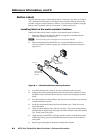
6. Disconnect the Power and RJ-45 cables from the MTP signal generator and
reconnect them to the MTP transmitter.
7. Repeat steps 1 through 6 for each input.
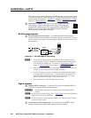
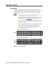
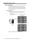
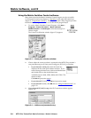
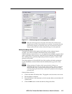
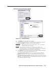
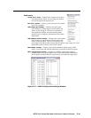
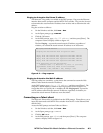
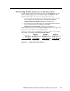
If, for any reason, you choose not to auto calibrate, or if you want to fine tune the
adjustment, you can manually set the values as follows:
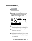
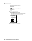
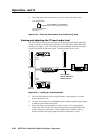
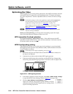
8. Connect an oscilloscope (preferred) or a monitor (acceptable) to local output
(VGA output) 1.
9. If using an oscilloscope, apply a white field test pattern to the input to be
optimized via an MTP transmitter.
If using a monitor, apply a grayscale or Color Bars test pattern to the input to
be optimized via an MTP transmitter.
H
TheExtronVTG300orVTG400arerecommendedtoprovidethetestpattern.
10. Tie the input to be optimized to output 1.
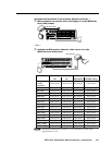
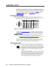
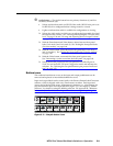
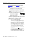
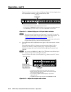
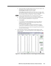
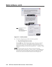
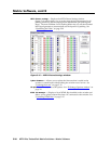
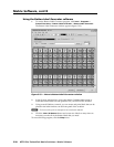
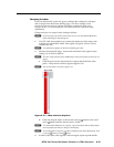
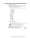
11. Observe the oscilloscope or the monitor with a critical eye while you adjust
the input level/peaking setting to compensate for signal loss between the
transmitter and the MTPX.
12. If necessary, repeat steps 8 through 11 for each input.
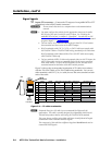
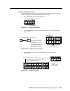
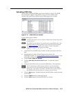
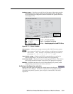
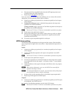
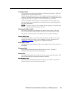
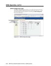
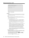
MTPX skew setting
The MTPX has skew adjustments on the inputs and the outputs. Both should be
set to compensate for signal skew across all ties. Adjust input and output skew as
follows:
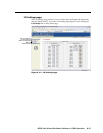
Inputs:
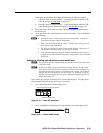
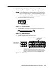
1. Connect an oscilloscope (preferred) or a monitor (acceptable) to local output
(VGA output) 1.
2. Apply a crosshatch test pattern to the input to be optimized via an MTP
transmitter.
H
TheExtronVTG300orVTG400arerecommendedtoprovidethetestpattern.
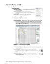
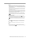
3. Tie the input to be optimized to output 1.
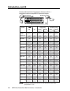
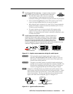
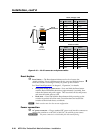
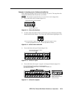
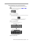
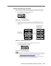
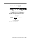
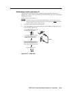
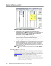
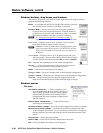
4. Use the test equipment or examine the displayed video image with a critical
eye to determine which video signal — red, green, or blue — is most shifted
to the left.
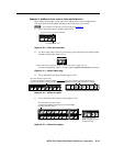
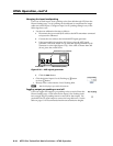
5. Adjust the leftmost video signal to the right until all three colors are properly
converged.
N
Whentheskewadjustmentissettozero,theMTPXPluscannotshiftthe
rightmost video image to the left.
N
A2-nanosecondadjustmentisveryne.Upto10nanosecondsofdelaymaybe
necessary before you detect a change in the display.
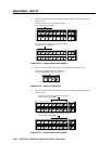
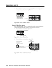
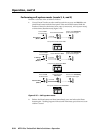
6. If either of the two the remaining colors is left shifted, repeat steps 4 and 5.
7. Repeat steps 2 through 6 for all other inputs.
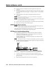
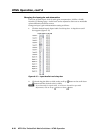
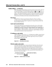
Outputs:
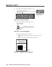
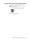
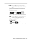
8. Connect an oscilloscope (preferred) or a monitor (acceptable) to the TP output
to be adjusted, via an MTP receiver.
9. Apply a crosshatch test pattern to one the local (VGA) inputs.
H
TheExtronVTG300orVTG400arerecommendedtoprovidethetestpattern.