MTPX Plus Twisted Pair Matrix Switchers • Operation
3-2
Operation
Front Panel Controls and Indicators
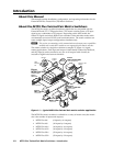
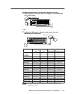
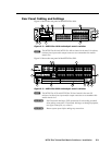
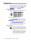
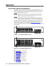
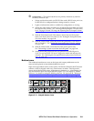
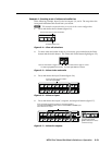
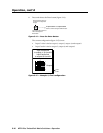
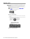
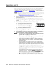
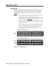
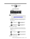
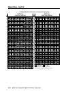
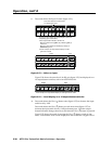
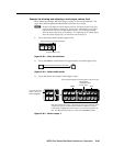
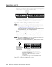
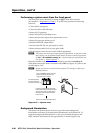
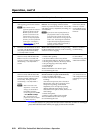
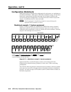
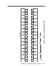
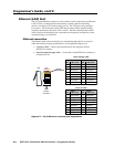
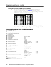
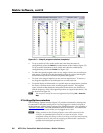
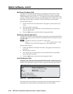
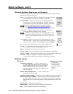
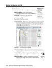
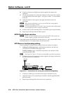
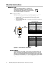
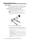
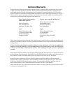
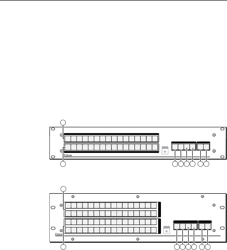
The front panel controls (figure 3-1 and figure 3-2) are grouped into two sets. The
input and output buttons,
a
and
b
, are grouped on the left side of the control
panel. The control buttons and video/audio (I/O) selection buttons,
c
and
h
, are
grouped on the right side of the panel.
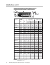
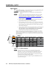
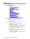
N
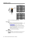
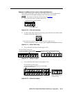
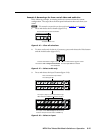
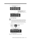
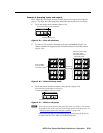
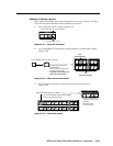
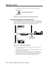
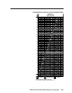
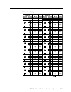
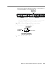
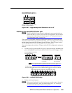
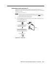
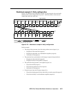
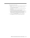
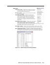
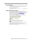
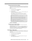
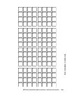
Whilethenumberofinputsandoutputsvariesdependingonthesizeofthe
matrix,thereareonlytwofrontpanelarrangements:16inputbuttonsby16
outputbuttons(gure3-1)and32by32(gure3-2).
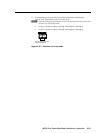
N
Onsmallermatrixswitchers,thelarger-numberedbuttonsarenotusedfor
input and output selection, although they are used to select and indicate preset
numbers, indicate the input audio level, and indicate the output audio volume.
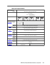
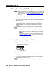
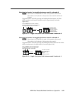
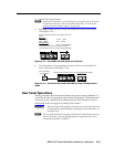
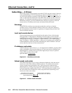
The large, illuminated pushbuttons can be labeled with text and/or graphics. The
buttons can be set to provide amber background illumination all the time, or the
background illumination can be turned off (see “Background illumination”, on
page3-48).Thebuttonsblinkorarelitatfullintensity(dependingontheoperation)
when selected.
AUDIO
VIDEO
I/O
CONTROL
ENTER PRESET
VIEW
ESC
1
2
3
4
5
6
7
8
9
10
11
12
13
14
15
16
1
2
3
4
5
6
7
8
9
10
11
12
13
14
15
16
INPUTS
OUTPUTS
CONFIG
MTPX PLUS SERIES
MTP MATRIX SWITCHER
5 6 7 8
1
Figure 3-1 — Front panel, MTPX Plus 1616
MTPX PLUS SERIES
MTP MATRIX SWITCHER
1
2
3
4
5
6 7
8
9
10
11 12
13 14 15 16
17
18
19
20
21
22 23
24
25
26
27 28
29 30 31 32
O
U
T
P
U
T
S
1
2
3
4
5
6
7 8
9
10
11
12
13 14 15 16
17
18
19
20
21
22 23
24
25
26
27 28
29 30 31 32
I
N
P
U
T
S
CONTROL I/O
CONFIG
ENTER PRESET
VIEW
ESC
VIDEO AUDIO
5 6 7 8
1
2 3 4
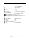
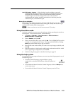
Figure 3-2 — Front panel, MTPX Plus 3232
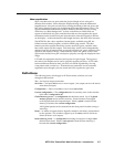
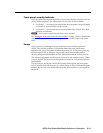
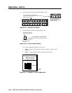
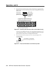
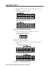
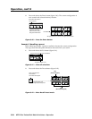
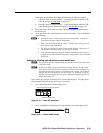
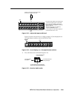
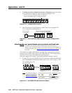
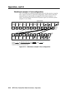
a
Input buttons — See page 3-4.
b
Output buttons — See page 3-4.
c
Enter button — See page 3-5.
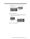
d
Preset button —Seepage3-6.
e
View button —Seepage3-6.
f
Esc button — See page 3-7.
g
Video button —Seepage3-8.
h
Audio button — See page 3-9.