2-5
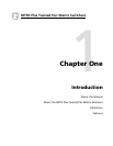
MTPX Plus Twisted Pair Matrix Switchers • Installation
b
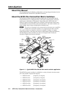
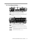
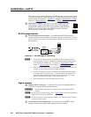
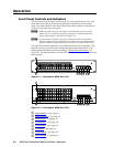
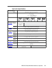
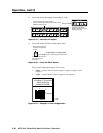
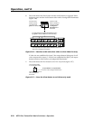
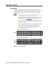
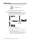
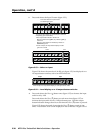
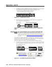
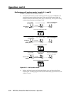
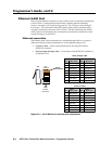
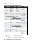
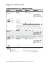
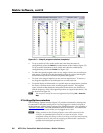
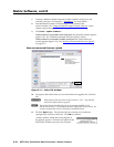
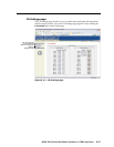
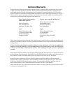
Local Inputs (VGA) connectors — Connect analog computer-
video (RGB) sources to these 15-pin HD female connectors.
N
• The video that is input on this connector is converted
totheproprietaryTPsignaloutputbytheMTP15HD
transmitters, allowing you to eliminate some of the transmitters in your system.
•
Extron recommends againsttyingalocal(VGA)inputtoalocal(VGA)
output;theimagedisplayedfromsuchatiemaybeoverpeaked.
•
Wheneithertheinputoroutputofatieislocal(VGA),Extronrecommends
that the MTP output or input be connected by a minimum of 50' (15 m) of
TP cable
to prevent o
verpeaking.
•
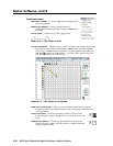
ThematrixswitcherscanalsoinputandswitchHDcomponentvideo,
component video, S-video, or composite video by using the appropriate
adapters.Nocongurationoftheswitcherisrequiredforcomponentorother
non-RGBvideoformats.
c
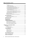
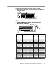
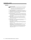
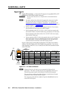
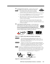
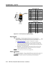
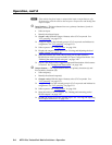
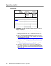
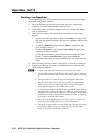
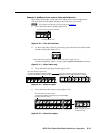
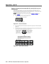
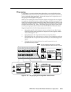
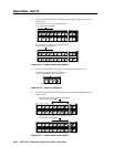
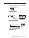
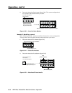
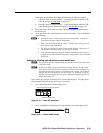
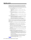
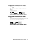
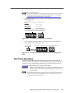
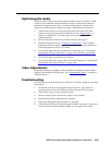
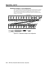
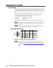
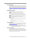
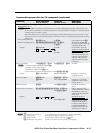
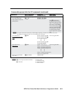
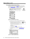
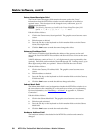
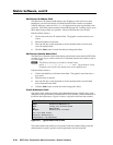
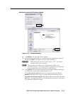
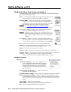
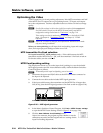
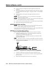
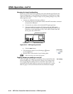
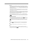
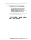
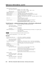
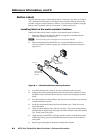
Audio Inputs (local audio) connectors — Connect balanced or
unbalanced stereo audio inputs to these 3.5 mm, 5-pole captive
screw connectors. Connectors are included with each switcher,
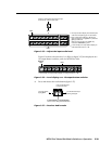
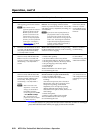
but you must supply the audio cable. See figure 2-5 to wire a
connector for the appropriate input type and impedance level.
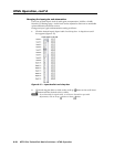
Use the supplied tie-wrap to strap the audio cable to the extended tail of the
connector.Highimpedanceisgenerallyover800ohms.
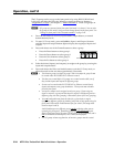
L R
L R
Unbalanced Stereo Input
Balanced Stereo Input
(high impedance)
(high impedance)
Do not tin the wires!
Ring
Sleeve (s)
Tip
Sleeve
Tip
Sleeve
Tip
Tip
Ring
Figure 2-5 — Captive screw connector wiring for audio inputs
C
The length of the exposed (stripped) portion of the copper wires is
important. The ideal length is 3/16” (5 mm). Longer bare wires can
short together. Shorter bare wires are not as secure in the captive screw
connectors and could be pulled out.
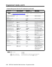
C
The captive screw audio connector can easily be inadvertently plugged
partially into one receptacle and partially into an adjacent receptacle. This
misconnection could damage the audio output circuits. Ensure that the
connector is plugged fully and only into the desired input or output.
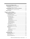
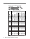
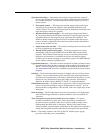
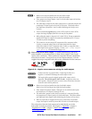
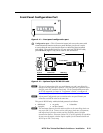
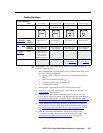
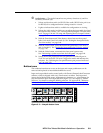
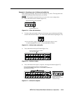
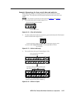
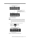
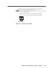
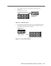
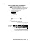
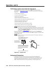
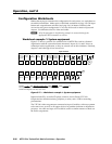
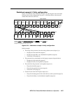
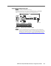
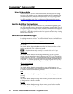
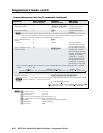
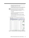
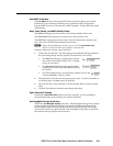
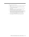
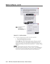
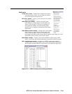
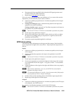
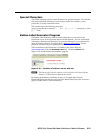
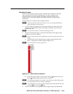
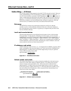
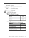
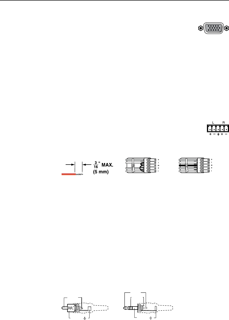
N
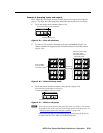
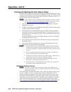
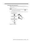
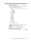
Seegure2-6toidentifythetip,ring,andsleevepartsoftheconnectorwhen
you are making connections for the switcher from existing audio cables. A mono
audio connector consists of a tip and sleeve. A stereo audio connector consists
of a tip, ring and sleeve. The ring, tip, and sleeve wires are also shown on the
captivescrewaudioconnectordiagrams,gure2-5andgure2-8.
Tip (+)
Sleeve ( )
Sleeve ( )
Ring (
-
)
Tip (+)
RCA Connector
3.5 mm Stereo Plug Connector
(balanced)
Figure 2-6 — Typical audio connectors
See Ray Hall/Paul Mellough for adding note:
“It is recommended that when connecting up
an audio source to the Local Audio Input, that
any unused input pins be connected to the
ground pin.”
This would apply to any conguration, other
than balanced stereo where all pins are used.”
My question is, what unused input pins
should be tied to ground? The only unused
one is ground.
Stet per P. Mellough, 9-11-2008