3-9
MTPX Plus Twisted Pair Matrix Switchers • Operation
h
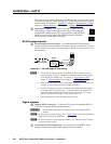
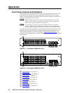
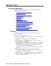
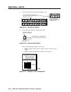
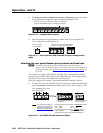
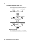
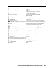
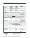
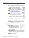
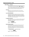
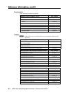
Audio button —TheAudiobuttonhastwoprimaryfunctions(•)andve
secondary functions (❏):
• Selectsanddeselectsaudio(orRS-232iftheaudio/RS-232wirepairisset
for RS-232) for a configuration that is being created or viewed.
• Lightstoindicatethataudioisavailableforcongurationorviewing.
❏ Selects the Audio mode, in which you can adjust the input audio level and
the output audio volume. See “Viewing and adjusting the TP input audio
level” on page 3-34 and “Viewing and adjusting the local output volume”
on page 3-40.
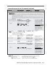
❏ With the Enter button and Video button, selects between front panel
locks (Lock mode 2 and Lock mode 0). See “Setting the front panel locks
(Executivemodes)”onpage3-46.
❏ With the Video button, selects between front panel locks (Lock mode 2
and Lock mode 1). See “Setting the front panel locks (Executive modes)”
onpage3-46.
❏ With the Video button, commands the front panel system reset.
See“Performingasystemresetfromthefrontpanel”onpage3-48.
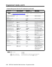
❏ Selects the RS-422 protocol for the rear panel RS-232/RS-422 port in
SerialPortandAudio/RS-232InputCongurationmode and indicates the
selection. See “Selecting the rear panel Remote port protocol and baud
rate” on page 3-50.
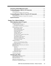
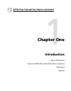
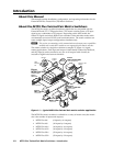
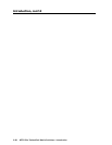
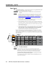
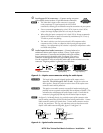
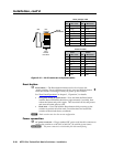
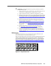
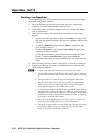
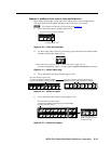
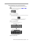
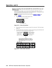
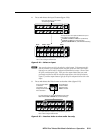
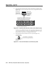
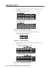
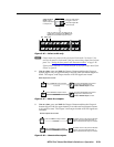
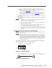
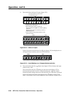
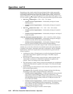
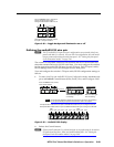
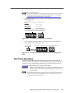
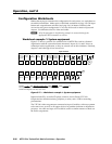
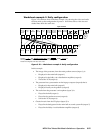
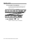
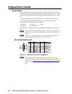
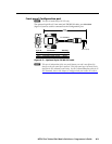
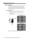
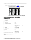
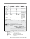
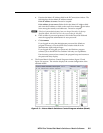
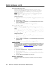
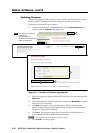
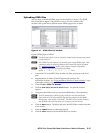
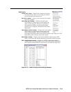
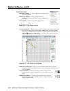
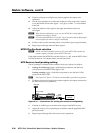
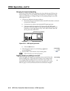
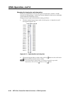
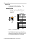
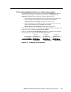
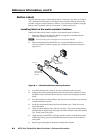
Button icons
The numbered translucent covers on the input and output pushbuttons can be
removed and replaced to insert labels behind the covers.
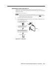
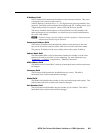
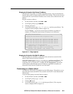
Input and output labels can be created easily with Extron’s Button-Label Generator
software, which is shipped with every Extron matrix switcher. Each input and
output can be labeled with names, alphanumeric characters, or . color bitmaps for
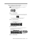
easy and intuitive input and output selection (figure 3-3). See chapter 5, “Matrix
Software”, for details on using the labeling software. See appendix B, “Reference
Information”, for blank labels and a procedure for removing and replacing the
translucent covers.
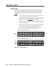
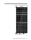
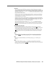
DVD
VCR
Computer Computer
Document
Camera
VTG 200
10 13 15
2928 30 31 32
I
N
P
U
T
S
Figure 3-3 — Sample button icons