HTML Operation, cont’d
MTPX Plus Twisted Pair Matrix Switchers • HTML Operation
6-14
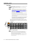
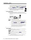
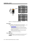
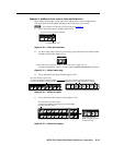
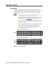
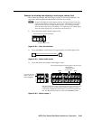
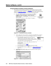
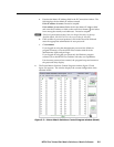
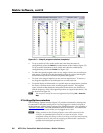
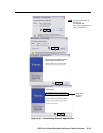
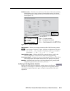
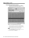
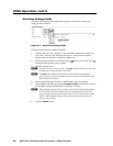
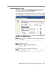
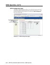
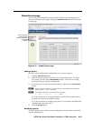
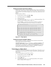
Changing the input level/peaking
Users can set each input’s level/peaking value (from 000 through 255) from the
Picture Settings page. Level/peaking can be adjusted to compensate for longer
cable runs on the inputs. Change an input’s level/peaking setting in any of the
following three ways:
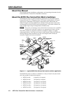
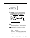
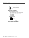
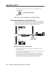
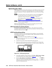
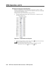
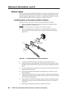
• Use the auto calibration function as follows:
1. Disconnect the power and RJ-45 cables at the MTP transmitter connected
to input to be calibrated.
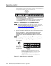
2. Connect the two cables to the included MTP signal generator.
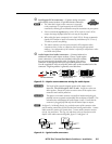
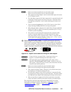
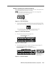
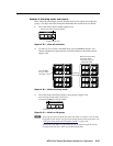
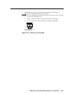
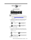
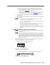
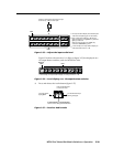
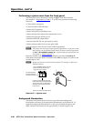
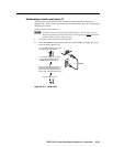
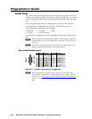
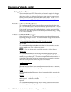
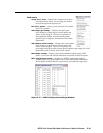
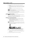
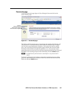
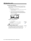
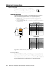
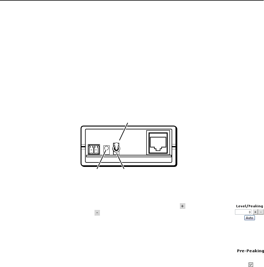
3. If the input cable is longer than 300' (90 m), place the MTP signal
generator’s Pre-Peak switch on (up when the signal generator‘s RJ-45
connectoristotheright[gure6-11]).Ifthecableisshorterthan300'
(90 m), place the switch down.
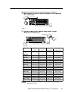
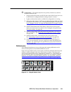
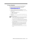
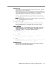
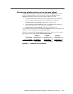
Pre-Peak on (up) (shown)
Pre-Peak off (down)Power LED
Figure 5-20 — MTP signal generator
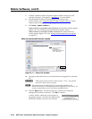
4. Click the Auto button.
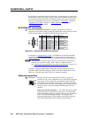
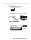
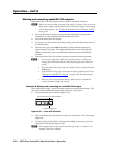
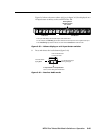
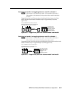
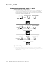
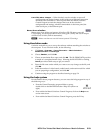
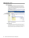
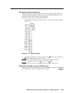
• Click the desired input’s Level/Peaking up
button
or down button.
• Directly enter a value into the Level/Peaking field.
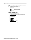
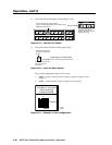
H
Watch a display as you make adjustments.
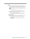
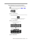
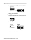
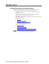
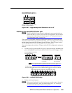
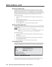
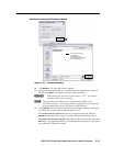
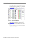
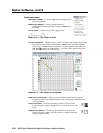
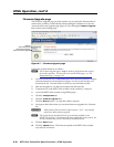
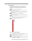
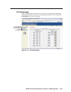
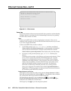
Toggling output pre-peaking on and off
Users can toggle each output’s pre-peaking value on and off from the
Picture Settings page. Click in the desire output’s Pre-Peaking check
box to toggle the pre-peaking feature on and off for that output. Pre-
peak alters the TP signal output to correct for long cable runs. See the
table on page 1-5 for recommended maximum transmission lengths.