


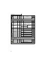

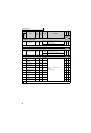

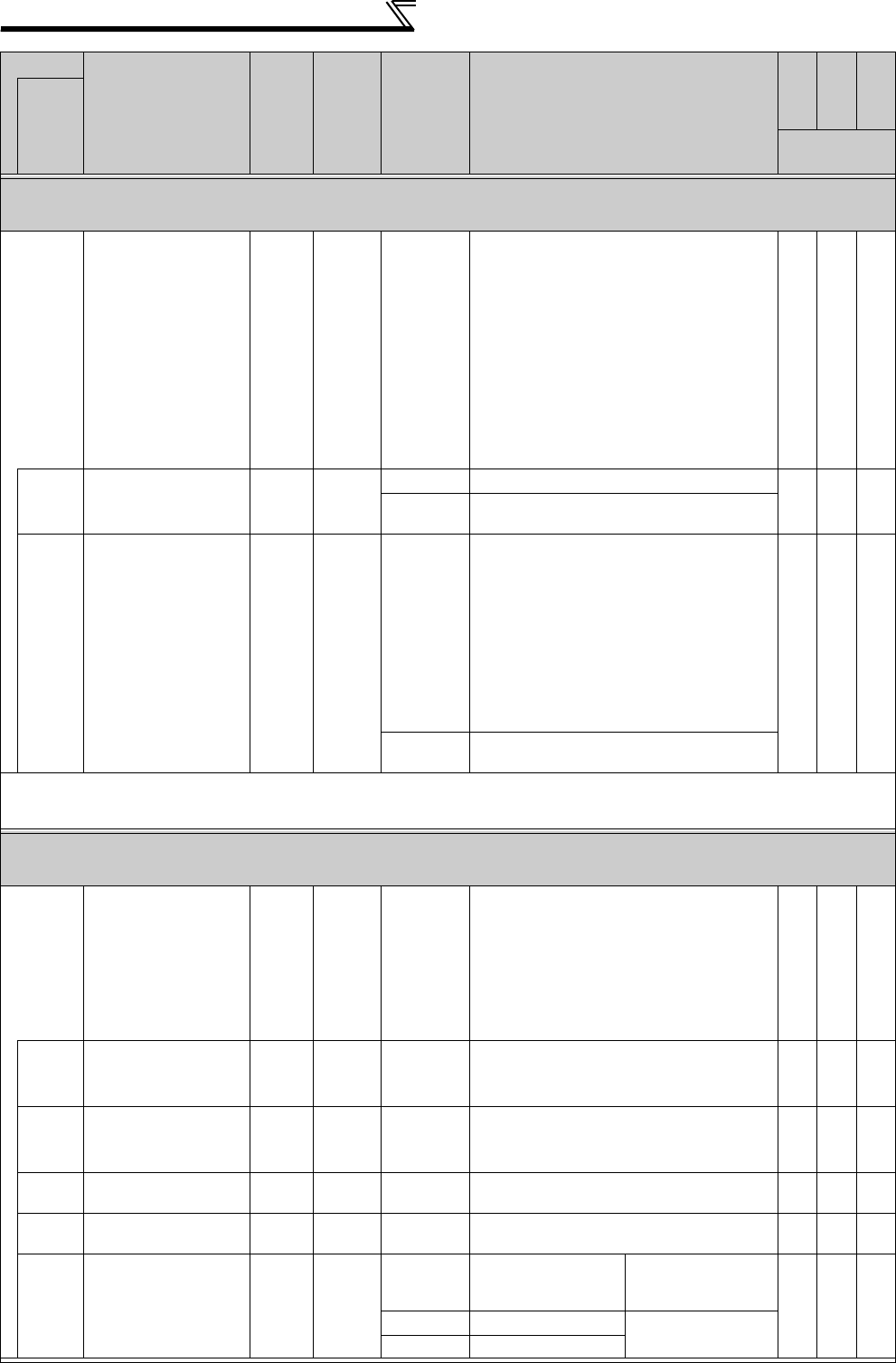
96
Parameter list
Motor noise suppression and measures against EMC and leakage current
—
Carrier frequency
and Soft-PWM selection (Pr.72, Pr.240, Pr.260)
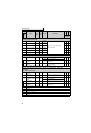
72
PWM frequency
selection
12
0 to 15/
0 to 6, 25
*1
•
V/F control, Simple magnetic flux vector control
PWM carrier frequency can be changed.
The setting is displayed in [kHz].
Note that 0 indicates 0.7kHz, 15 indicates
14.5kHz and 25 indicates 2.5kHz.
•IPM motor control
0 to 5 : 2kHz
6 to 9 : 6kHz
10 to 13 : 10kHz
14, 15 : 14kHz
Pr.72 cannot be set to "25" under IPM motor
control.
240
Soft-PWM operation
selection
11 *2
0Soft-PWM invalid
1
When Pr. 72 = "0 to 5" ("0 to 4" for the 75K or
higher), Soft-PWM is valid.
260
PWM frequency
automatic switchover
11 *3
0
PWM carrier frequency is constant
independently of load.
Under the following controls, perform
continuous operation at less than 85% of the
inverter rated current.
•
V/F control, Simple magnetic flux vector control
When the carrier frequency setting is 3kHz or
higher (Pr.72 ≥
3)
•IPM motor control
When the carrier frequency setting is 6kHz or
higher (Pr.72 ≥ 6)
1
Decreases PWM carrier frequency
automatically when load increases.
*1 The setting depends on the inverter capacity (55K or lower/75k or higher)
*2 Performing IPM parameter initialization changes the settings. (Refer to page 43)
*3 Performing IPM parameter initialization sets back the settings to the initial settings. (Refer to page 43)
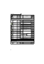
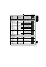
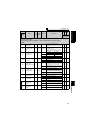
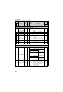
Frequency setting by analog input — Analog input selection, override function, analog
input compensation (Pr.73, Pr.242, Pr.243, Pr.252, Pr.253, Pr.267)
73
Analog input selection
11
0 to 7,
10 to 17
You can select the input specifications of terminal
2 (0 to 5V, 0 to 10V, 0 to 20mA) and input
specifications of terminal 1 (0 to ±5V, 0 to ±10V).
Override and reversible operation can be
selected. To change the terminal 2 to the voltage
input specification (0 to 5V/ 0 to 10V), turn
OFF(initial status) the voltage/current input
switch. To change it to the current input(0 to
20mA), turn ON the voltage/current input switch.
×
242
Terminal 1 added
compensation
amount (terminal 2)
0.1% 100% 0 to 100%
Set the ratio of added compensation amount
when terminal 2 is the main speed.
243
Terminal 1 added
compensation
amount (terminal 4)
0.1% 75% 0 to 100%
Set the ratio of added compensation amount
when terminal 4 is the main speed.
252
Override bias
0.1% 50% 0 to 200%
Set the bias side compensation value of
override function.
253
Override gain
0.1% 150% 0 to 200%
Set the gain side compensation value of
override function.
267
Terminal 4 input
selection
10
0
Terminal 4 input 4 to
20mA
Turn ON the voltage/
current input switch
(initial status).
×
1 Terminal 4 input 0 to 5V
Turn OFF the voltage/
current input switch.
2 Terminal 4 input 0 to 10V
Parameter
Name
Incre-
ments
Initial
Value
Range Description
Parameter
copy
Parameter
clear
All parameter
clear
Related
parameters
: enabled
× : disabled