


41
3
DRIVING THE IPM MOTOR <IPM>
Setting procedure of IPM motor control
<IPM>
3 DRIVING THE IPM MOTOR
<IPM>
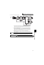
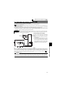
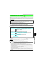
Highly efficient motor control and highly accurate motor speed control can be performed by using the inverter with an IPM
motor.
The motor speed is detected by the output voltage and current of the inverter. It does not require a speed detector such as an
encoder. The inverter drives the IPM motor with the least required current when a load is applied in order to achieve the
highest motor efficiency.
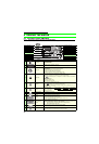
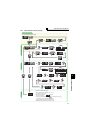
3.1 Setting procedure of IPM motor control
<IPM>
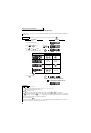
* IPM parameter initialization is performed by setting Pr. 998 IPM parameter initialization or by selecting (IPM parameter initialization) on the
operation panel.
To change to the IPM motor control, perform IPM parameter initialization at first. If parameter initialization is performed after setting other
parameters, some of those parameters will be initialized too. (Refer to page 43 for the parameters that are initialized.)
POINT
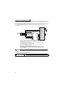
The following conditions must be met to perform IPM motor control.
· For the motor model, dedicated IPM motor (MM-EFS model or MM-EF model) must be used.
·
The motor capacity must be equivalent to the inverter capacity. (The 0.75K inverter can be used with the 0.4kW
MM-EF
.)
· Single-motor operation (one motor run by one inverter) must be performed.
· The overall wiring length with the motor must be 100m or less.
· This inverter is set for a general-purpose motor in the initial setting. Follow the following procedure to change the setting for the
IPM motor control.
REMARKS
· "Er1" appears if IPM parameter initialization is performed while Pr.72 = "25."
· To use a 0.4kW MM-EF, set Pr.80 Motor capacity = "0.4" before setting IPM parameter initialization.
CAUTION
· For the setting range of a speed command under dedicated IPM motor (MM-EFS 1500r/min specification, MM-EF 1800r/min
specification) controls, refer to the output frequency range in Chapter 8.2 Common specifications (Refer to page 152).
· The selectable carrier frequencies under IPM motor control are 2k, 6k, 10k, and 14kHz.
· Constant-speed operation cannot be performed in the low-speed range lower than 150r/min (MM-EFS 1500r/min specification) or
180r/min (MM-EF 1800r/min specification). Generally, speed control can be performed in the range that satisfies the ratio, 1:10.
· During IPM motor control, the RUN signal is output about 100ms after turning ON the start command (STF, STR). The delay is
due to the magnetic pole detection.
· The following operations and controls are disabled during IPM motor control: adjustable 5 points V/F, bypass sequence,
energy saving operation, Optimum excitation control, and speed smoothing.
· The option surge voltage suppression filter (FR-ASF-H/FR-BMF-H) and sine wave filter (MT-BSL/BSC) cannot be used under
IPM motor control, so do not connect them.
· When parameter copy is performed from a FR-F700P series inverter, which is set to use MM-EFS under IPM motor control,
check that IPM motor control is selected on the operation panel (P.RUN is lit) after the copy. When parameters are copied to a
FR-F700P series inverter, which is not compatible with MM-EFS, Simple magnetic flux vector control is selected instead of IPM
motor control.
IPM
IPM
IPM
IPM
IPM
IPM
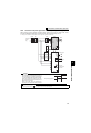
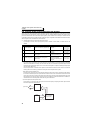
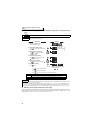
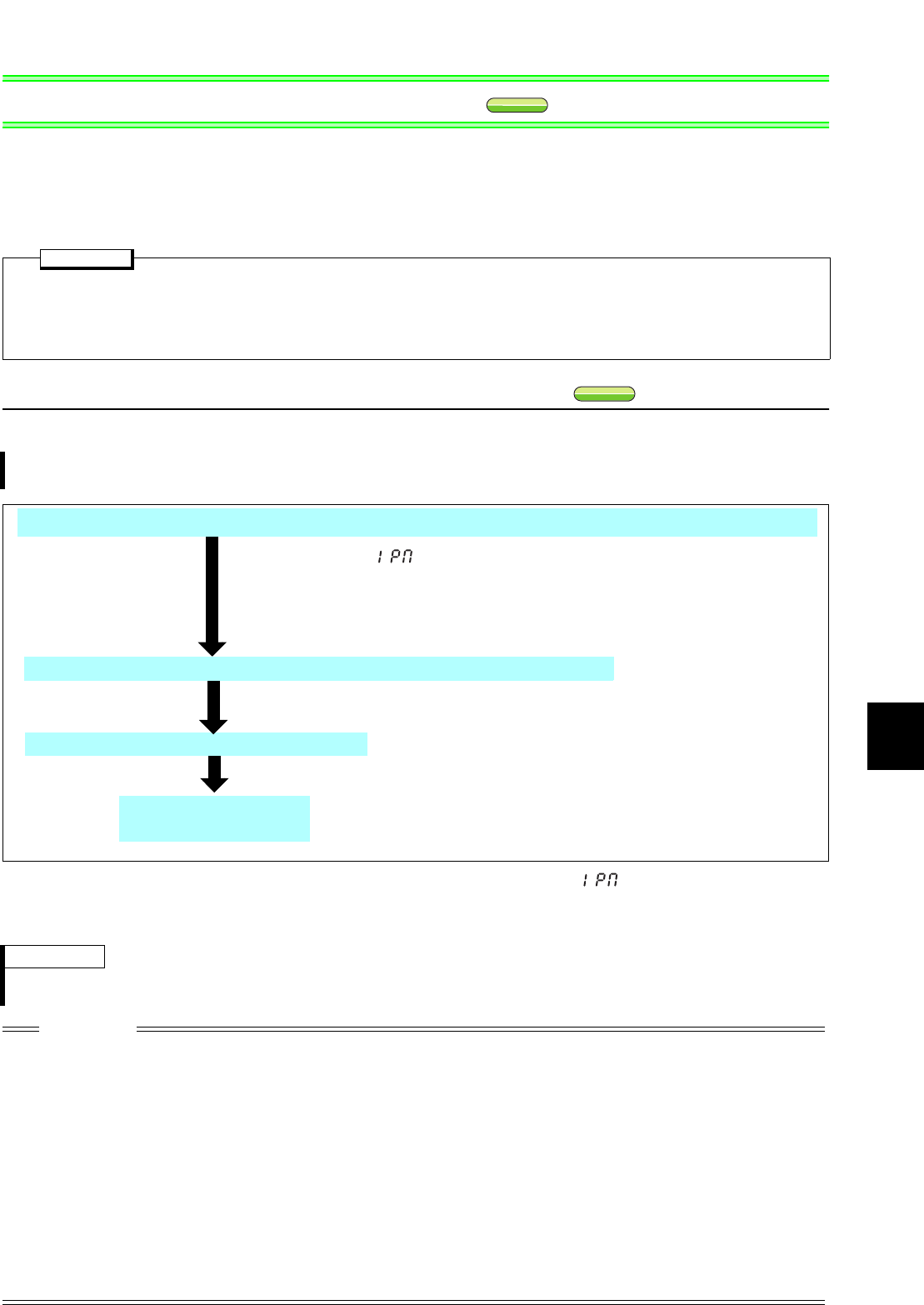
Test run
Perform IPM parameter initialization by selecting the parameter setting mode (IPM) on the operation panel.*
(Refer to page
42
)
Set the operation command. (Refer to page 78)
Set "1" or "12" in (IPM parameter initialization) to select IPM motor
control. Refer to page 42 for the setting method.
Setting value "1": MM-EF
Setting value "12": MM-EFS
P.RUN on the operation panel (FR-DU07) is lit when IPM motor control is set.
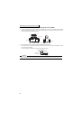
Set parameters such as the acceleration/deceleration time and multi-speed setting.
Set parameters such as the acceleration/deceleration time and multi-
speed setting as required.
Select the start command and speed command.