


37
Power-OFF and magnetic contactor
(MC)
2
INSTALLATION AND WIRING
2.6 Power-OFF and magnetic contactor (MC)
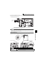
(1) Inverter input side magnetic contactor (MC)
On the inverter input side, it is recommended to provide an MC for the following purposes.
(
Refer to page 4 for selection.)
1)To release the inverter from the power supply when the fault occurs or when the drive is not functioning (e.g.
emergency stop operation).
2)
To prevent any accident due to an automatic restart at restoration of power after an inverter stop made by a power failure
3)To separate the inverter from the power supply to ensure safe maintenance and inspection work
The inverter's input side MC is used for the above purpose, select class JEM1038-AC3MC for the inverter input side
current when making an emergency stop during normal operation.
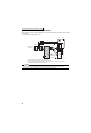
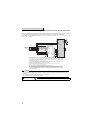
(2) Handling of the inverter output side magnetic contactor
Switch the magnetic contactor between the inverter and general-purpose motor only when both the inverter and motor
are at a stop. When the magnetic contactor is turned ON while the inverter is operating, overcurrent protection of the
inverter and such will activate. When using a magnetic contactor to switch to a commercial power supply while using a
general-purpose motor, it is recommended to use the bypass operation Pr. 135 to Pr. 139. (Refer to Chapter 4 of the
Instruction Manual (Applied)).
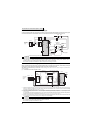
REMARKS
Since repeated inrush current at power ON will shorten the life of the converter circuit (switching life is 100 million times (about
500,000 times for the 200V class 37K or higher)), frequent starts/stops must be avoided. Turn ON/OFF the inverter start
controlling terminals (STF, STR) to run/stop the inverter.
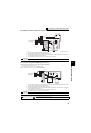
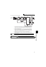
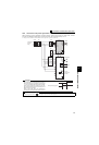
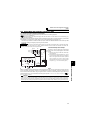
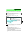
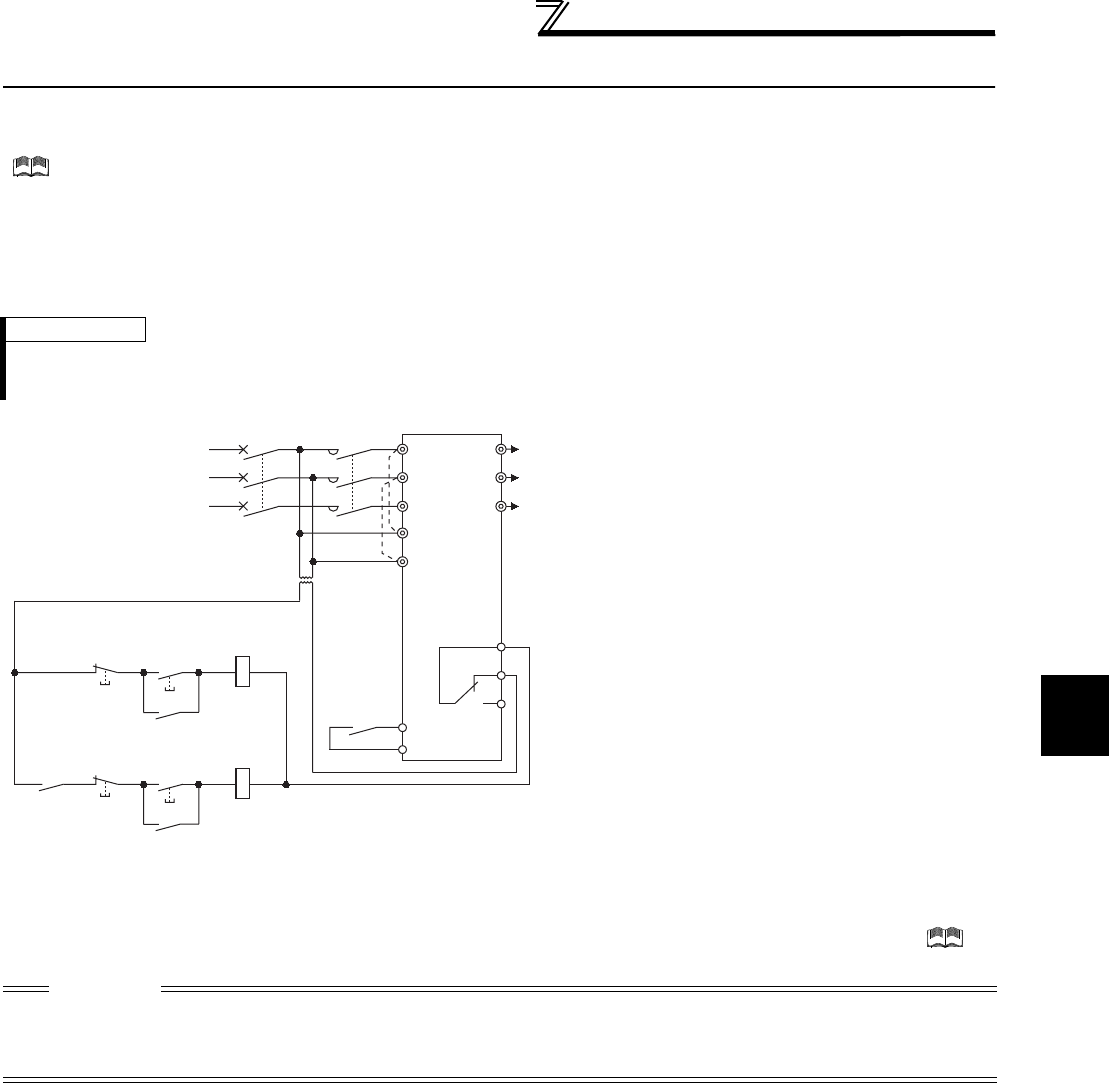
• Inverter start/stop circuit example
As shown on the left, always use the start signal
(ON or OFF of STF (STR) signal) to make a start
or stop.
*1 When the power supply is 400V class, install a step-
down transformer.
*2 Connect the power supply terminals R1/L11, S1/L21
of the control circuit to the primary side of the MC to
hold an alarm signal when the inverter's protective
circuit is activated. At this time, remove jumpers
across terminals R/L1 and R1/L11, and S/L2 and S1/
L21. (Refer to page 18 for removal of the jumper.)
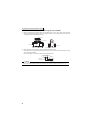
CAUTION
IPM motor is a synchronous motor with high-performance magnets embedded in the rotor. Motor terminals hold high-voltage while the
motor is running even after the inverter power is turned OFF. Before wiring or inspection, the motor must be confirmed to be stopped.
When the motor is driven by the load in applications such as fan and blower, a low-voltage manual contactor must be connected at the
inverter's output side, and wiring and inspection must be performed while the contactor is open. Otherwise you may get an electric shock.
Power
supply
MCCB
RA
U
V
A1
B1
C1
W
To the
motor
Inverter
MC
STF/STR
R/L1
S/L2
T/L3
R1/L11
S1/L21
OFF
ON
MC
Stop
Start
RA
MC
Operation preparation
Start/Stop
MC
RA
SD
T
*1
*2