


17
Wiring
2
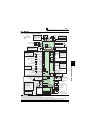
INSTALLATION AND WIRING
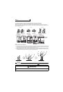
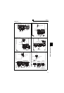
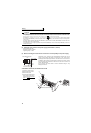
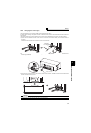
(2) Notes on earthing (grounding)
• Leakage currents flow in the inverter. To prevent an electric shock, the inverter and motor must be earthed (grounded). This
inverter must be earthed (grounded). Earthing (Grounding) must conform to the requirements of national and local safety
regulations and electrical codes. (NEC section 250, IEC 536 class 1 and other applicable standards)
A neutral-point earthed (grounded) power supply for 400V class inverter in compliance with EN standard must be used.
• Use the dedicated earth (ground) terminal to earth (ground) the inverter.
(Do not use the screw in the casing, chassis, etc.)
• Use the thickest possible
earth (ground)
cable. Use the cable whose size is equal to or greater than that indicated in
page
15
and minimize the cable length. The earthing (grounding) point should be as near as possible to the inverter.
To be compliant with the EU Directive (Low Voltage Directive), earth (ground) the inverter according to
the instructions on page 171.
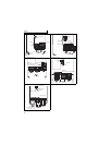
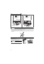
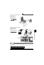
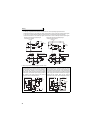
(3) Total wiring length
Under general-purpose motor control
Connect one or more general-purpose motors within the total wiring length shown in the following table.
When driving a 400V class motor by the inverter, surge voltages attributable to the wiring constants may occur at the
motor terminals, deteriorating the insulation of the motor. Take the following measures 1) or 2) in this case.
1) Use a "400V class inverter-driven insulation-enhanced motor" and set frequency in Pr. 72 PWM frequency selection
according to wiring length.
2) Connect the surge voltage suppression filter (FR-ASF-H/FR-BMF-H) to the 55K or lower and the sine wave filter
(MT-BSL/BSC) to the 75K or higher on the inverter output side.
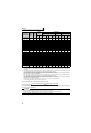
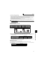
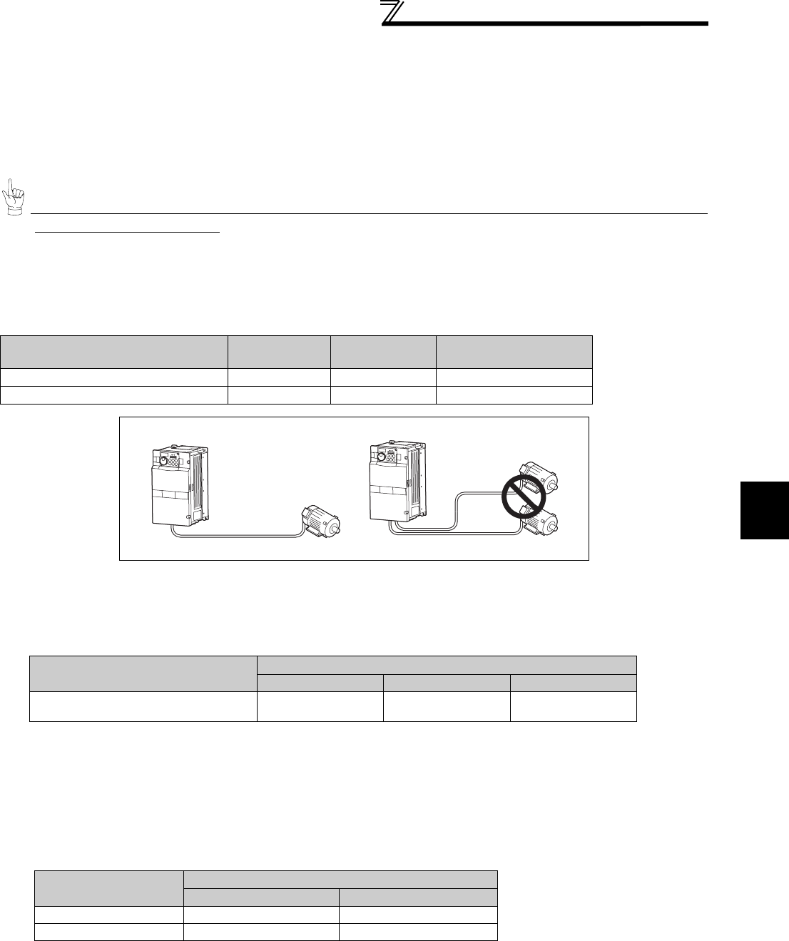
Under IPM motor control
Connect an IPM motor within the total wiring length of 100m.
Use one dedicated IPM motor for one inverter. Multiple IPM motors cannot be connected to an inverter.
To drive a 400V-class motor with an inverter under IPM control, set Pr.72 PWM frequency selection according to the wiring
length as shown below.
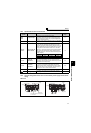
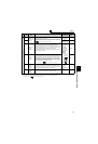
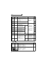
Pr. 72 PWM frequency selection Setting
(carrier frequency)
0.75K 1.5K 2.2K or Higher
2 (2kHz) or lower 300m 500m 500m
3 (3kHz) or higher 200m 300m 500m
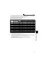
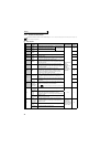
Total wiring length when using a general-purpose motor (2.2K or higher)
Applied inverter
Wiring Length
50m or less 50m to 100m
FR-F740P-0.75K to 1.5K 0(2kHz) to 15(14kHz) 5(2kHz) or lower
Other 0(2kHz) to 15(14kHz) 9(6kHz) or lower
500m or less
300m
300m
300m + 300m = 600m
Wiring Length
50m or less 50m to 100m exceeding 100m
Pr. 72 PWM frequency selection Setting
(carrier frequency)
14.5kHz or lower 9kHz or lower 4kHz or lower