


127
6
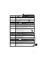
TROUBLESHOOTING
Causes and corrective actions
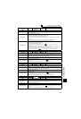
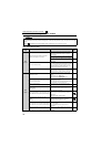
Operation Panel
Indication
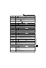
E.PTC
FR-PU04 Fault 14
FR-PU07 PTC activated
Name
PTC thermistor operation
Description
Trips when the motor overheat status is detected for 10s or more by the external PTC thermistor input
connected to the terminal AU.
This fault is available when "63" is set in Pr. 184 AU terminal function selection and AU/PTC switchover
switch is set in PTC side. When the initial value (Pr. 184 = "4") is set, this protective function is not
available.
Check point
· Check the connection between the PTC thermistor switch and thermal relay protector.
· Check the motor for operation under overload.
· Is valid setting ( = 63) selected in Pr. 184 AU terminal function selection ? ( Refer to Chapter 4 of the
Instruction Manual (Applied).)
Corrective action
Reduce the load weight.
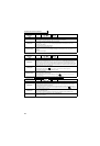
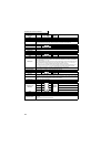
Operation Panel
Indication
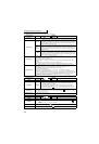
E.OPT
FR-PU04
FR-PU07
Option Fault
Name
Option fault
Description
· Appears when the AC power supply is connected to the terminal R/L1, S/L2, T/L3 accidentally when
a high power factor converter is connected.
· Appears when the switch for the manufacturer setting of the plug-in option is changed.
· Appears when a communication option is connected while Pr. 296 Password lock level = "0 or 100."
Check point
· Check that the AC power supply is not connected to the terminal R/L1, S/L2, T/L3 when a high
power factor converter (FR-HC, MT-HC) or power regeneration common converter (FR-CV) is
connected.
· Check if password lock is activated by setting Pr. 296 = "0, 100"
Corrective action
· Check the parameter (Pr. 30) setting and wiring.
· The inverter may be damaged if the AC power supply is connected to the terminal R/L1, S/L2, T/L3
when a high power factor converter is connected. Please contact your sales representative.
· Return the switch for the manufacturer setting of the plug-in option to the initial status. ( Refer to
Chapter 4 of the Instruction Manual (Applied).)
· To apply the password lock when installing a communication option, set Pr.296 ≠ "0,100". ( Refer
to Chapter 4 of the Instruction Manual (Applied).).
· If the problem still persists after taking the above measure, please contact your sales representative.
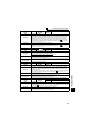
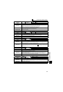
Operation Panel
Indication
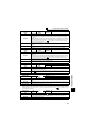
E.OP1
FR-PU04
FR-PU07
Option 1 Fault
Name
Communication option fault
Description
Stops the inverter output when a communication line fault occurs in the communication option.
Check point
· Check for a wrong option function setting and operation.
· Check that the plug-in option is plugged into the connector securely.
· Check for a break in the communication cable.
· Check that the terminating resistor is fitted properly.
Corrective action
· Check the option function setting, etc.
· Connect the plug-in option securely.
· Check the connection of communication cable.
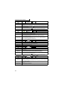
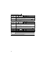
Operation Panel
Indication
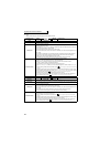
E. 1
FR-PU04
FR-PU07
Fault 1
Name
Option fault
Description
Stops the inverter output if a contact fault or the like of the connector between the inverter and
communication option occurs.
Appears when the switch for the manufacturer setting of the plug-in option is changed.
Check point
· Check that the plug-in option is plugged into the connector securely.
· Check for excess electrical noises around the inverter.
Corrective action
· Connect the plug-in option securely.
· Take measures against noises if there are devices producing excess electrical noises around the
inverter.
If the problem still persists after taking the above measure, please contact your sales representative
or distributor.
· Return the switch position for the manufacturer setting of the plug-in option to the initial status. (
Refer to instruction manual of each option)