


125
6
TROUBLESHOOTING
Causes and corrective actions
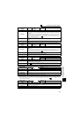
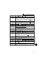
Operation Panel
Indication
E.IPF
FR-PU04
FR-PU07
Inst. Pwr. Loss
Name
Instantaneous power failure
Description
If a power failure occurs for longer than 15ms (this also applies to inverter input shut-off), the instantaneous
power failure protective function is activated to trip the inverter in order to prevent the control circuit from
malfunctioning. If a power failure persists for longer than 100ms, the fault output is not provided, and the
inverter restarts if the start signal is ON upon power restoration. (The inverter continues operating if an
instantaneous power failure is within 15ms.) In some operating status (load magnitude, acceleration/
deceleration time setting, etc.), overcurrent or other protection may be activated upon power restoration.
When instantaneous power failure protection is activated, the IPF signal is output.
(
Refer to Chapter 4
of
the Instruction Manual (Applied))
Check point
Find the cause of instantaneous power failure occurrence.
Corrective action
· Remedy the instantaneous power failure.
· Prepare a backup power supply for instantaneous power failure.
· Set the function of automatic restart after instantaneous power failure (Pr. 57). ( Refer to Chapter 4
of the Instruction Manual (Applied).)
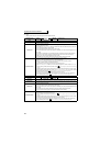
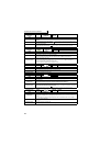
Operation Panel
Indication
E.BE
FR-PU04
FR-PU07
Br. Cct. Fault
Name
Brake transistor alarm detection/internal circuit fault
Description
This function stops the inverter output if a fault occurs in the brake circuit, e.g. damaged brake
transistors when using functions of the 75K or higher.
In this case, the inverter must be powered OFF immediately.
For the 55K or lower, it appears when an internal circuit error occurred.
Check point
· Reduce the load inertia.
· Check that the frequency of using the brake is proper.
· Check that the brake resistor selected is correct.
Corrective action
For the 75K or higher, when the protective function is activated even if the above measures are taken,
replace the brake unit with a new one.
For the 55K or lower, replace the inverter.
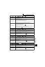
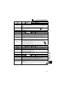
Operation Panel
Indication
E.UVT
FR-PU04
FR-PU07
Under Voltage
Name
Undervoltage
Description
If the power supply voltage of the inverter decreases, the control circuit will not perform normal functions.
In addition, the motor torque will be insufficient and/or heat generation will increase. To prevent this, if
the power supply voltage decreases below about 150V (300VAC for the 400V class), this function
stops the inverter output.
When a jumper is not connected across P/+ and P1, the undervoltage protective function is activated.
When undervoltage protection is activated, the IPF signal is output. ( Refer to Chapter 4 of the
Instruction Manual (Applied))
Check point
· Check for start of large-capacity motor.
· Check that a jumper or DC reactor is connected across terminals P/+ and P1.
Corrective action
· Check the power supply system equipment such as the power supply.
· Connect a jumper or DC reactor across terminals P/+ and P1.
· If the problem still persists after taking the above measure, please contact your sales representative.
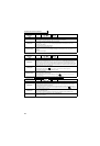
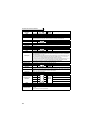
Operation Panel
Indication
E.ILF
FR-PU04 Fault 14
FR-PU07 Input phase loss
Name
Input phase loss
Description
This fault is output when function valid setting (=1) is set in Pr. 872 Input phase loss protection selection
and one phase of the three phase power input is lost.
When the setting of Pr. 872 Input phase loss protection selection is the initial value (Pr. 872 = "0"), this fault
does not occur. ( Refer to Chapter 4 of the Instruction Manual (Applied).)
Check point
Check for a break in the cable for the three-phase power supply input.
Corrective action
· Wire the cables properly.
· Repair a break portion in the cable.
· Check the Pr. 872 Input phase loss protection selection setting.