


8
Installation of the inverter and instructions
2.3 Installation of the inverter and instructions
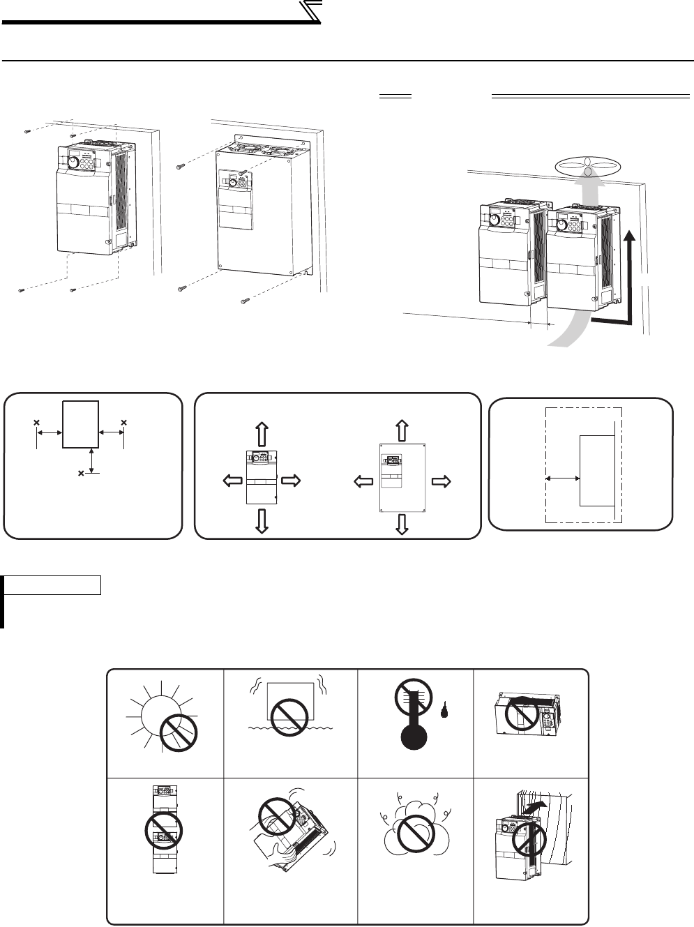
• Installation of the Inverter
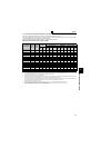
• Install the inverter under the following conditions.
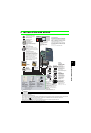
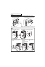
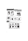
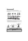
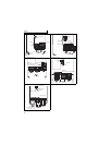
• The inverter consists of precision mechanical and electronic parts. Never install or handle it in any of the following
conditions as doing so could cause an operation fault or failure.
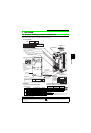
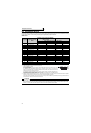
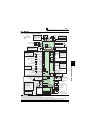
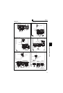
Installation on the enclosure
30K or lower 37K or higher
*1cm or more for 3.7K or lower
REMARKS
•
For replacing the cooling fan of the FR-F740P-185K or higher, 30cm of space is necessary in front of the inverter.
Refer to page 146 for fan replacement.
CAUTION
⋅ When encasing multiple inverters, install them in
parallel as a cooling measure.
⋅ Install the inverter vertically.
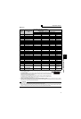
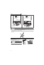
Refer to the clearances below.
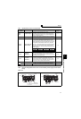
Vertical
Fix six points for the FR-F740P-185K
to 400K and fix eight points for the
FR-F740P-450K to 560K.
Clearances
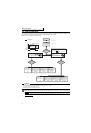
Surrounding air temperature and humidity
Measurement
position
Measurement
position
Inverter
Leave enough clearances as a
cooling measure.
Humidity: 90% RH maximum
55K or lower 75K or higher
5cm
5cm
5cm
10cm or more
20cm or more
20cm or more
10cm or more
5cm
or more *
5cm
or more *
10cm
or more
10cm
or more
Temperature: -10°C to 50°C
(front)
*1cm or more for 3.7K or lower
Clearances (side)
*
Inverter
5cm
or more
Direct sunlight
High temperature,
high humidity
Horizontal placement
Mounting to
combustible material
Oil mist, flammable
gas, corrosive gas,
fluff, dust, etc.
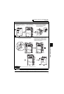
Transportation by
holding the front cover
Vertical mounting
(When installing two or
more inverters, install
them in parallel.)
Vibration(5.9m/s
2
* or more at 10 to
55Hz (directions of X, Y, Z axes))
*2.9m/s
2
or more for the 185K or
higher