


110
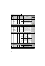
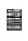
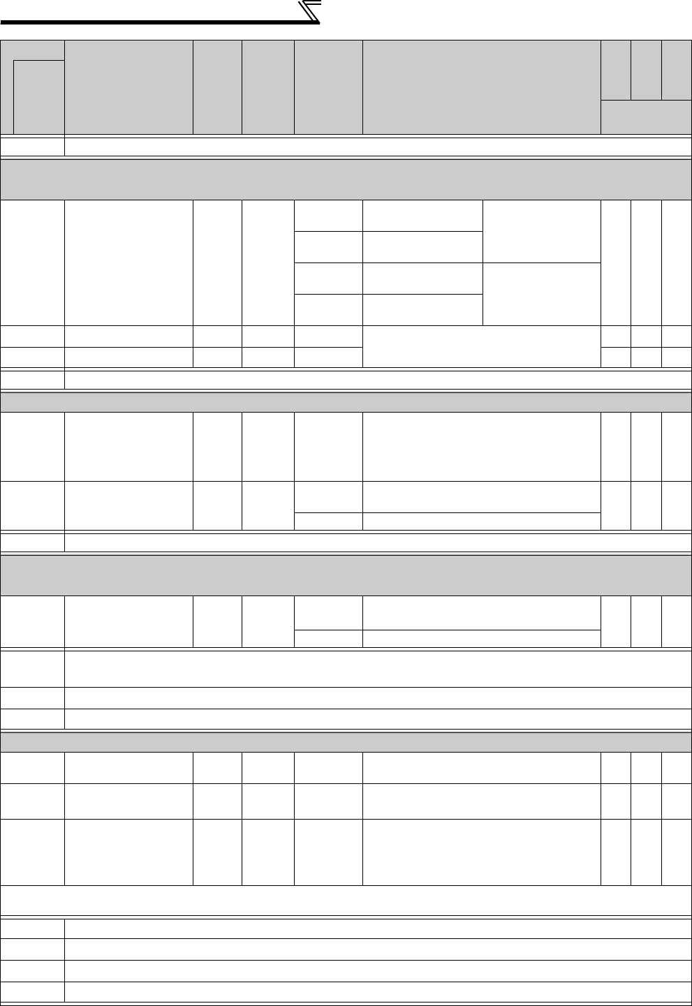
Parameter list
340
Refer to Pr.79.
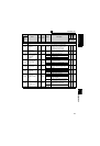
Function assignment of external terminal and control — Remote output function (REM
signal) (Pr.495 to Pr.497)
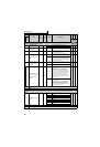
495
Remote output
selection
10
0
Remote output data
clear at powering OFF
Remote output data is
cleared during an
inverter reset
1
Remote output data
held at powering OFF
10
Remote output data
clear at powering OFF
Remote output data is
retained during an
inverter reset
11
Remote output data
held at powering OFF
496
Remote output data 1
1 0 0 to 4095
Output terminal can be switched ON and OFF.
×××
497
Remote output data 2
1 0 0 to 4095
×××
502
Refer to Pr.331.
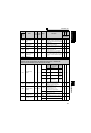
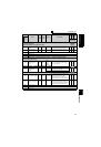
Useful functions — Maintenance of parts (Pr.503, Pr.504)
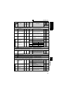
503
Maintenance timer
10
0 (1 to 9998)
Displays the cumulative energization time of
the inverter in 100h increments.
Reading only
Writing the setting of "0" clears the cumulative
energization time.
×××
504
Maintenance timer
alarm output set time
1 9999
0 to 9998
Set the time taken until when the maintenance
timer alarm output signal (Y95) is output.
×
9999 No function
505
Refer to Pr.37.
Motor brake and stop operation — Coast to stop at the specified frequency or lower
(Pr.522)
522
Output stop
frequency
0.01Hz
9999
0 to 400Hz
Set the frequency to start coasting to a stop
(output shutoff).
9999 No function
539, 549,
550
Refer to Pr.331 to Pr.339, Pr.341 to Pr.343.
551
Refer to Pr.117 to Pr.124, Pr.331 to Pr.339, Pr.341 to Pr.343.
553, 554
Refer to Pr.127 to Pr.134.
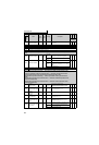
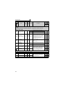
Useful functions — Current average value monitor signal (Pr.555 to Pr.557)
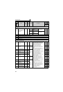
555
Current average time
0.1s 1s 0.1 to 1.0s
Set the time taken to average the current
during start bit output (1s).
556
Data output mask
time
0.1s 0s 0.0 to 20.0s
Set the time for not obtaining (mask) transient
state data.
557
Current average
value monitor signal
output reference
current
0.01/
0.1A
*1
Rated
inverter
current
*2
0 to 500/
0 to 3600
A *1
Set the reference (100%) for outputting the sig-
nal of the current average value.
*1 Setting increments and setting range differ according to the inverter capacity. (55K or lower/75K or higher)
*2 Performing IPM parameter initialization changes the settings. (Refer to page 43)
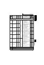
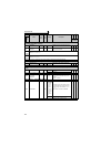
563, 564
Refer to Pr.52.
571
Refer to Pr.13.
575 to 577
Refer to Pr.127 to Pr.134.
611
Refer to Pr.57 and Pr.58.
Parameter
Name
Incre-
ments
Initial
Value
Range Description
Parameter
copy
Parameter
clear
All parameter
clear
Related
parameters
: enabled
× : disabled