


89
Parameter list
Parameter list
5
ADJUSTMENT
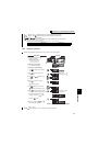
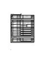
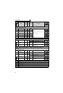
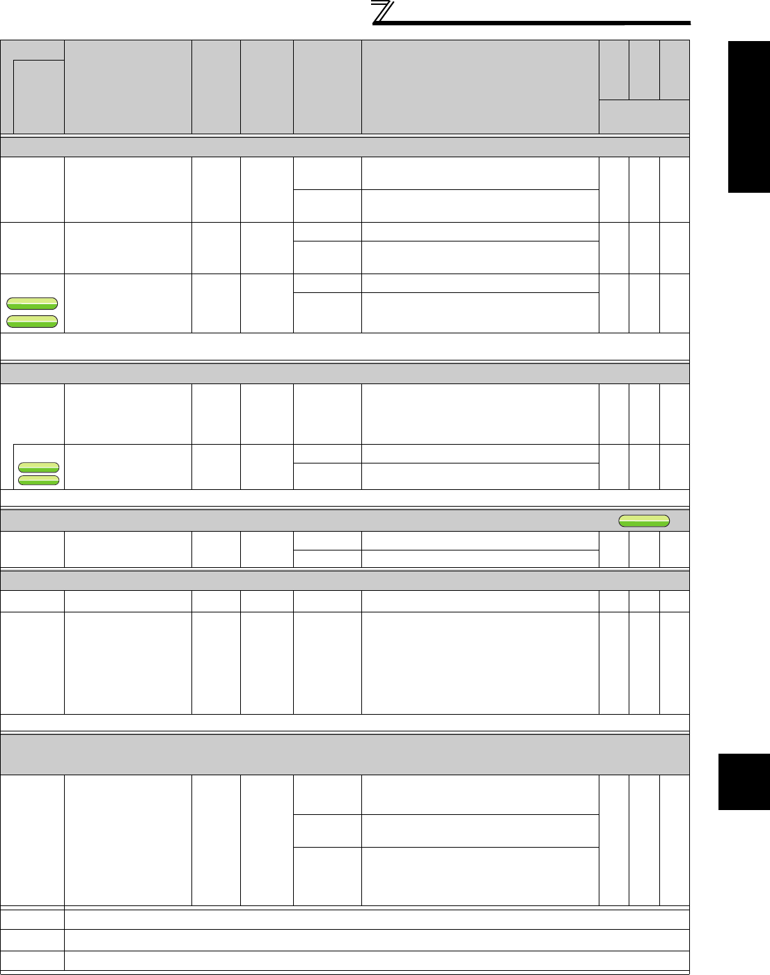
Motor brake and stop operation — DC injection brake (Pr.10 to Pr.12)
10
DC injection brake
operation frequency
0.01Hz 3Hz
0 to 120Hz
*1
Set the operation frequency of the DC injection
brake.
9999
Operate when the output frequency becomes
less than or equal to Pr.13 Starting frequency.
11
DC injection brake
operation time
0.1s 0.5s
0 DC injection brake disabled
0.1 to 10s
Set the operation time of the DC injection
brake.
12
DC injection brake
operation voltage
0.1%
4/2/1%
*2
0 DC injection brake disabled
0.1 to 30% Set the DC injection brake voltage (torque).
*1 Under IPM motor control, the frequency is fixed at 0Hz even if Pr.11 ≠ "0."
*2 Initial values differ according to the inverter capacity. (7.5K or lower/11K to 55K/75K or higher)
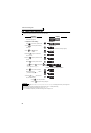
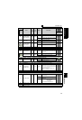
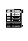
Acceleration/deceleration time/pattern adjustment — Starting frequency (Pr.13, Pr.571)
13
Starting frequency
0.01Hz 0.5Hz
*
0 to 60Hz
Starting frequency can be set.
If the set frequency is set higher than the start
frequency under IPM motor control, the output
starts at 0.01Hz.
571
Holding time at a start
0.1s 9999
0.0 to 10.0s
Set the holding time of Pr.13 Starting frequency.
9999 Holding function at a start is invalid
* Performing IPM parameter initialization changes the settings.(Refer to page 43)
V/F pattern setting — V/F pattern suitable for the application (Pr.14)
14
Load pattern selection
11
0 For constant-torque load
1 For reduced-torque load
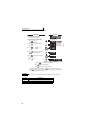
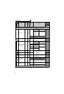
Frequency setting with terminals (contact input) — Jog operation (Pr.15, Pr.16)
15
Jog frequency *
0.01Hz 5Hz
*
0 to 400Hz Set the frequency for jog operation.
16
Jog acceleration/
deceleration time
0.1/
0.01s
0.5s
0 to 3600/
360s
Set the acceleration/deceleration time for jog
operation. Set the time taken to reach the
frequency set in Pr.20 Acceleration/deceleration
reference frequency for acceleration/deceleration
time. (Initial value is 60Hz
*
)
In addition, acceleration/deceleration time
cannot be set separately.
* Performing IPM parameter initialization changes the settings.(Refer to page 43)
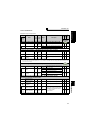
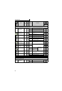
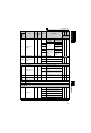
Function assignment of external terminal and control — Logic selection of the output stop
signal (MRS) (Pr.17)
17
MRS input selection
10
0 Open input always
2
Normally closed input (NC contact input
specifications)
4
External terminal:Normally closed input
(NC contact input
specifications)
Communication: Normally open input
18
Refer to Pr.1 and Pr.2.
19
Refer to Pr.3.
20, 21
Refer to Pr.7 and Pr.8.
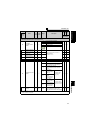
Parameter
Name
Incre-
ments
Initial
Value
Range Description
Parameter
copy
Parameter
clear
All parameter
clear
Related
parameters
: enabled
× : disabled
V/F
V/F
V/F
S
MFVC
S
MFVC
S
MFVC
V/F
V/F
V/F
S
MFVC
S
MFVC
S
MFVC
V/F
V/F
V/F