


78
Selection of the start command and
frequency command sources (Pr. 79)
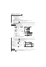
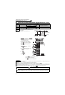
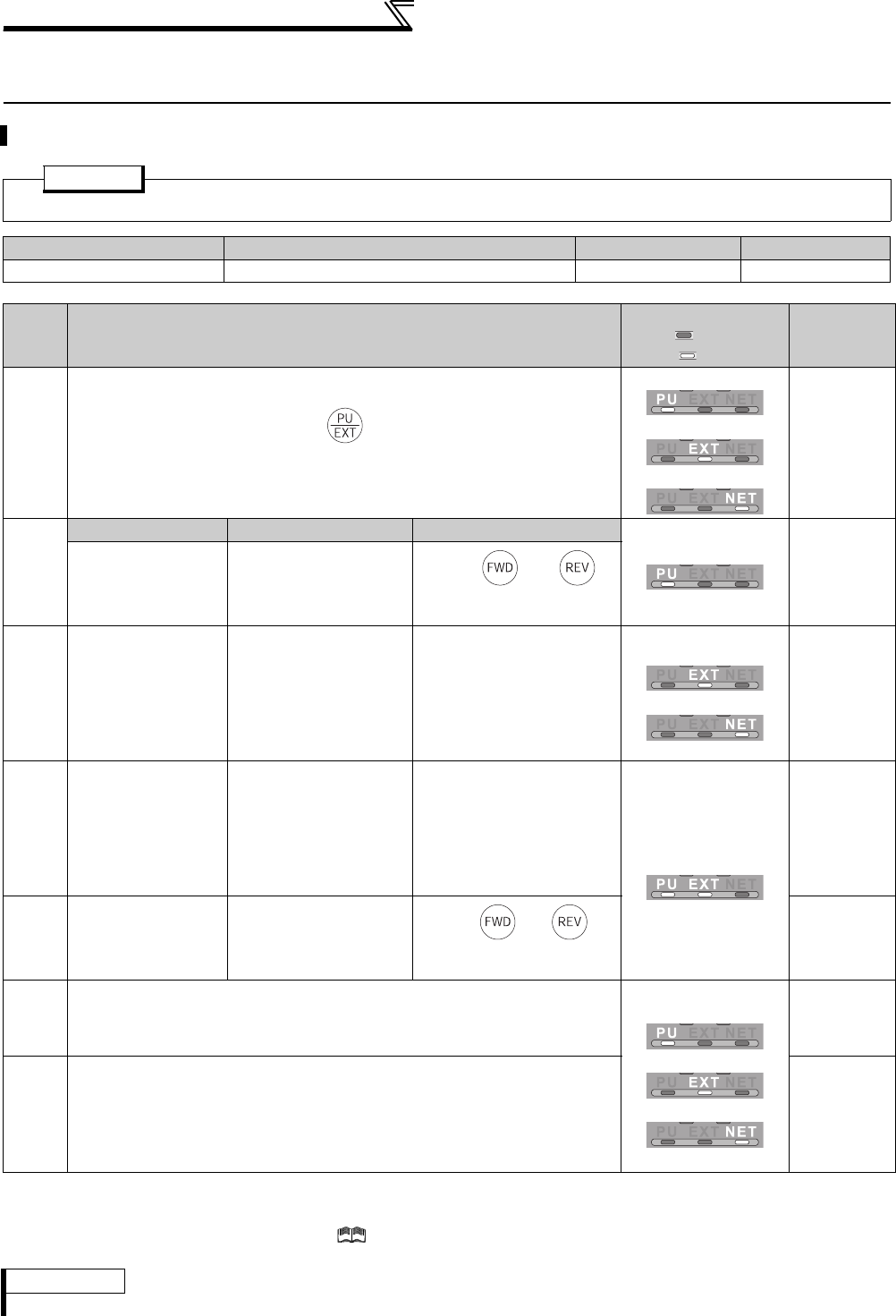
5.6 Selection of the start command and frequency command
sources (Pr. 79)
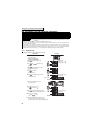
*1 The priorities of the frequency commands when Pr. 79 = "3" are "Multi-speed operation (RL/RM/RH/REX) > PID control (X14) > terminal 4 analog
input (AU) > digital input from the operation panel".
*2 For the terminal used for the X12 signal (PU operation interlock signal) input, set "12" in Pr. 178 to Pr. 189 (input terminal function selection) to assign
functions. For Pr. 178 to Pr. 189, refer to Chapter 4 of the Instruction Manual (Applied).
When the X12 signal is not assigned, function of the MRS signal switches from MRS (output stop) to PU operation interlock signal.
Select the start command source and frequency command source.
POINT
Setting value "1" to "4" can be changed in the easy setting mode. (Refer to page 48)
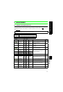
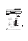
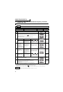
Parameter Number Name Initial Value Setting Range
79 Operation mode selection 0 0 to 4, 6, 7
Pr.79
Setting
Description
LED Indication
: OFF
: ON
Refer to
0
External/PU switchover mode (press to switch between the PU and
External operation mode.)
At power ON, the inverter is in the External operation mode.
PU operation mode
External operation mode
NET operation mode
Chapter 4 of
the Instruction
Manual
(Applied)
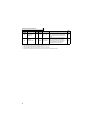
1
Operation mode Frequency command Start command
PU operation mode
Chapter 4 of
the Instruction
Manual
(Applied)
PU operation mode
(fixed)
Setting by the operation
panel (FR-DU07) and PU
(FR-PU04/FR-PU07)
Input by and
on PU (FR-DU07/FR-PU04/
FR-PU07)
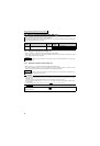
2
External operation
mode (fixed)
The operation can be
performed by
switching between
the External and NET
operation modes.
External signal input
(from terminal 2, 4, and
1, JOG, multi-speed
selection, etc.)
External signal input (from
terminal STF and STR)
External operation mode
NET operation mode
Chapter 4 of
the Instruction
Manual
(Applied)
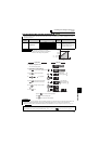
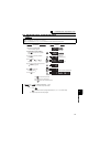
3
External/PU
combined operation
mode 1
PU (FR-DU07/FR-PU04/
FR-PU07) setting or
external signal input
(multi-speed setting,
across terminals 4 and 5
(valid when AU signal
turns ON)).
*1
External signal input (from
terminal STF and STR)
External/PU combined
operation mode
Chapter 4 of
the Instruction
Manual
(Applied)
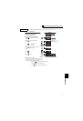
4
External/PU
combined operation
mode 2
External signal input
(Terminal 2, 4, 1, JOG,
multi-speed selection,
etc.)
Input by and on
PU (FR-DU07/FR-PU04/FR-
PU07)
Chapter 4 of
the Instruction
Manual
(Applied)
6
Switchover mode
Switch among PU operation, External operating, and NET operation while
keeping the same operating status.
PU operation mode
External operation mode
NET operation mode
Chapter 4 of
the Instruction
Manual
(Applied)
7
External operation mode (PU operation interlock)
X12 signal ON
*2
Operation mode can be switched to the PU operation mode.
(output stop during external operation)
X12 signal OFF
*2
Operation mode cannot be switched to the PU operation mode.
Chapter 4 of
the Instruction
Manual
(Applied)
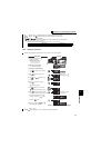
REMARKS
If switching of the operation mode is invalid even though Pr.79 is set, refer to page 138.