33
Connection of stand-alone option units
2
INSTALLATION AND WIRING
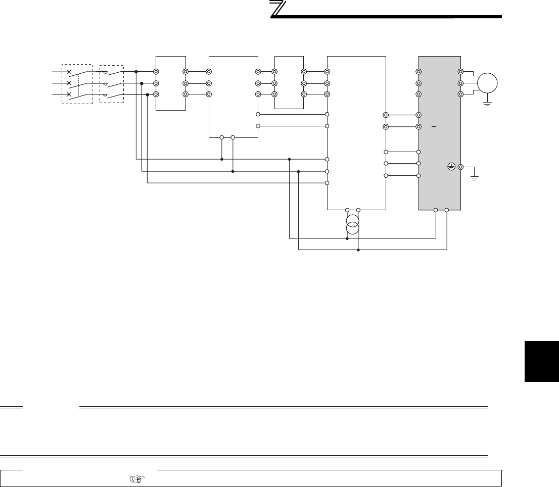
(2) Connection with the MT-HC (75K or higher)
*1 Remove the jumper across terminals R and R1, S and S1 of the inverter, and connect the control circuit
power supply to the R1 and S1 terminals. Do not connect anything to the power input terminals R/L1, S/
L2, and T/L3. Incorrect connection will damage the inverter. (E.OPT (option fault) will occur. (Refer to page
127.)
*2 Do not insert the MCCB between terminals P/+ and N/- (P/+ and P/+, N/- and N/-). Opposite polarity of
terminals N, P will damage the inverter.
*3 Use Pr. 178 to Pr. 189 (input terminal function selection) to assign the terminals used for the X10 (X11) signal.
(Refer to Chapter 4 of the Instruction Manual (Applied).) For communication where the start command is sent
only once, e.g. RS-485 communication operation, use the X11 signal when making setting to hold the
mode at occurrence of an instantaneous power failure. (Refer to Chapter 4 of the Instruction Manual
(Applied).)
*4 Connect the power supply to terminals R1 and S1 of the MT-HC via an isolated transformer.
*5 Be sure to connect terminal RDY of the MT-HC to the X10 signal or MRS signal assigned terminal of the
inverter, and connect terminal SE of the MT-HC to terminal SD of the inverter. Without proper connecting,
MT-HC will be damaged.
CAUTION
⋅ The voltage phases of terminals R/L1, S/L2, T/L3 and terminals R4, S4, T4 must be matched.
⋅ Use sink logic (initial setting) when the MT-HC is connected. The MT-HC cannot be connected when source logic is
selected.
⋅ When connecting the inverter to the MT-HC, do not connect the DC reactor provided to the inverter.
♦ Parameters referred to ♦
Pr.30 Regenerative function selection Refer to Chapter 4 of the Instruction Manual (Applied)
Three-phase
A
C power
supply
MCCB
MT-HCL01 MT-HCB
R1 S1
R1 S1
R1/
L11
S1/
L21
MT-HCL02 MT-HC Inverter
MT-HCTR
Isolated transformer
R
S
T
R/L1
S/L2
T/L3
U
V
W
R2
S2
T2
R2
S2
T2
R3
S3
T3
R3
S3
T3
R4
S4
T4
R4
S4
T4
R
S
T
88R
88S
88R
88S
*2
RDY
RSO
SE
X10
RES
SD
*3
*5
*1
*1
*4
Motor
M
P
N
P/+
N/
MC


