


25
Model PH90 Operating Procedures
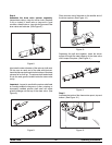
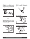
Step 4
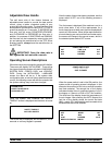
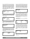
Assemble t he draw valve spinner assembly.
Inspect draw valve o--rings for cuts or nicks. (Replace
if cut or nicked.) If draw valve o--rings are in good
condition, slide the two o--r ings into the grooves of the
draw valve and lubricate. (See Figure 8.)
Figure 8
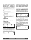
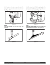
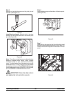
Lubricate the outer diameter of the spinner shaft seal.
Fill the cups on each end of the seal with lubricant.
Insert the spinner shaft seal into the bottom of the draw
valve as far as it will go. The spinner shaft seal should
fit into the seal groove located inside the draw valve
cavity.
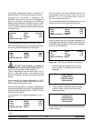
Important: Inspect to see that the spinner shaft seal
is correctly installed in the groove. A worn, missing, or
improperly installed spinner shaft seal will cause
product leakage out the top of the draw valve. (See
Figure 9 .)
Figure 9
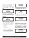
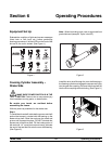
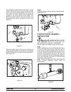
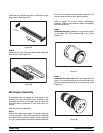
Place an even coat of lubricant on the smaller end of
the driven spinner. (See Figure 10.)
Figure 1 0
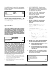
Squeezing the split end t ogether, insert the driven
spinner through the metal opening of the draw valve
until it snaps into place. (See Figure 11.)
Figure 11
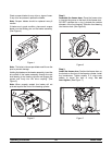
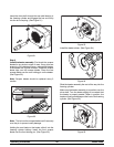
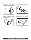
Step 5
Lubricate the inside of the freezer door spout, top and
bottom. (See Figure 12.)
Figure 1 2