


33
Model PH90 Operating Procedures
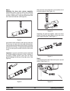
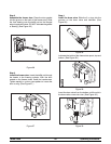
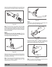
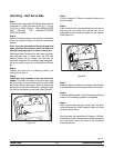
Insert the already assembled piston and valve body
into the bottom of the pump cylinder. (See Figure 43.)
Figure 4 3
Note: The drive hole in the piston must be visible
through the drive hole opening in the pump cylinder
and the aligning ball located at the base of the valve
body must be positioned into the notch at the bottom
of the pump cylinder .
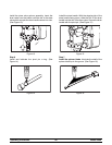
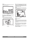
Step 6
Assemble the mix inlet tube assembly. Slide the
o--ring and seal into the grooves on the fittings and
thoroughly lubricate. (See Figure 44.)
Figure 4 4
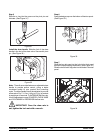
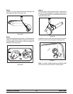
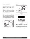
Attach the spring and poppet to the end of the pressure
relief fitting. The spring must be securely fastened and
not allowed to float freely.
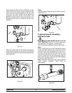
Note: The spring and rubber poppet act as a pressure
relief valve to prevent a pressure build up in the
freezing cylinder. (See Figure 45.)
Figure 4 5
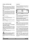
Step 7
Insert the mix inlet tube assembly into the hole i n the
base of the valve body. (See Figure 46.)
Figure 4 6
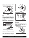
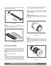
Secure the pump parts in position by sliding the
retaining pin through the cross holes located at the
bottom of the pump cylinder. (See Figure 47.)
Figure 4 7
Note: The head of the retaining pin should be facing
UP with the pump correctly installed.