


58
Model PH90Operating Procedures
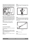
Step 1
Remove the syrup lines from the syrup ports, and
remove the restrictor cap from the bottom o f the door
spout.
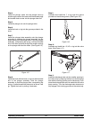
Step 2
Remove the spinner blade from the bottom of the door
spout by lifting up the plunger nut on the s pinner
coupling and pulling down the blade.
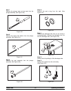
Step 3
Remove the handscrews, freezer door, beater
assembly with drive shaft seal andscraper blades from
the freezing cylinder.
Step 4
Remove the drive shaft seal from the drive shaft of the
beater assembly.
Step 5
Remove the freezer door o--r ing, front bearing, pivot
pin, draw handle and draw valve spinner assembly.
Remove o--r ing from pivot pin.
Disassemble the draw valve s pinner assembly.
Remove the driven spinner by grasping the draw valve
and pulling the driven spinner out. Remove the spinner
shaft seal.
Remove the two o--rings from the d raw valve.
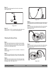
Step 6
From the shake pump cylinder, remove the retaining
pin, valve body, piston, spring and poppet, and the mix
inlet tube. Remove all o--r ings and check rings.
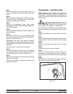
Step 7
Remove the drive shaft from the drive hub in the rear
wall of the mix hopper.
Remove the two small o--rings and one large o--r ing
from the drive shaft.
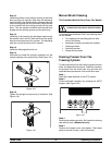
Disassembly -- Soft Serve Side
Note: Failure to remove parts, brush clean and
re--lubricate these parts, will result in damage to the
related parts. These parts must be removed every 14
days or the machine will lockout and not operate in the
AUTO mode.
MAKE SURE POWER SWITCH IS IN THE
“OFF ” POSITION. Failure to do so may cause injury
from hazardous moving parts, or electrocution.
With the parts tray available for the soft serve side,
remove the following parts and place them in the parts
tray.
Step 1
Remove the design cap from the bottom of the door
spout.
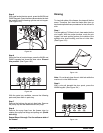
Step 2
Remove the handscrews, freezer door, beater, shoes,
scraper blades, and drive shaft from the freezing
cylinder.
Step 3
Remove the scraper blade clips from the scraper
blades.
Step 4
Remove the pivot pin and draw handle.
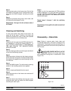
Step 5
From the soft serve pump cylinder, remove the
retaining pin, valve body, piston, spring and poppet,
and the mix inlet tube. Remove all o--r ings and check
rings.
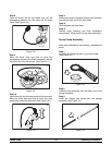
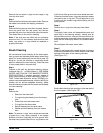
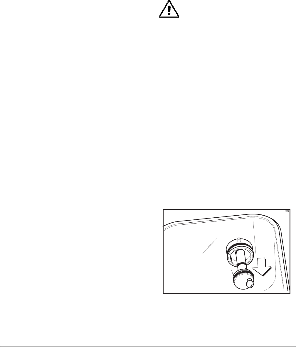
Step 6
Remove the drive shaft from the drive hub in the rear
wall of the mix hopper. (See Figure 126.)
Figure 126