


Theory of Operation 3M-Matic 800rf Case Sealer
5-2 Copyright 1999, 3M IPC. All rights reserved.
During normal operation, as the box exits the case
sealer it blocks the light path of the sixth photocell
momentarily. When the box clears this light path, the
controller allows the next box to enter the machine.
If cartons accumulate on the customers exit con-
veyor, a box may be blocked and unable to exit the
case sealer, or a box may be pushed back into the
machine. In either case, the light path of the sixth
photocell is blocked. If it remains blocked for more
than a few seconds, the infeed gate stays up and the
rollers stop, preventing more boxes from being fed
into the case sealer until the blockage is removed.
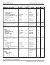
5-2-2. Fixed Mode
Use Fixed mode to run boxes through the machine
that are all the same height. The upper head assembly
stays down and is locked in the position determined
by the first box run through the machine in Fixed
mode.
The Fixed mode flap folding and box taping pro-
cesses operate the same as in Random mode. How-
ever, the side belt drive assemblies move out at the
beginning of the cycle rather than at the end of the
cycle. This allows the infeed gate to move down and
admit the next box before the previous box has left
the side belt drive assemblies.
The time saved by entering the next box early and by
not raising and lowering the upper head assembly
speed up the throughput of the machine.
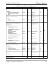
5-2-3. Bypass Mode
Use Bypass mode to run boxes through the machine
without folding the upper flaps or taping them;
however, the bottom of the box will be taped. The
upper head assembly remains fully raised. In Bypass
mode, the infeed gate and side belt drive assemblies
operate the same as in Random mode.
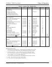
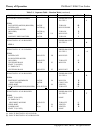
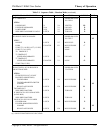
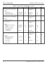
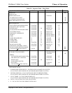
5-3. Sequence Tables
The sequence tables list specific events, and give the
order in which the events occur as a box passes
through the machine. Table 5-1 is the sequence table
for Random mode, Table 5-2 is for Fixed mode, and
Table 5-3 is for Bypass mode.
The table column headings are described below:
SEQUENCE
This column lists the initial operating conditions, the
events that occur when the RESET button is pressed,
the condition that initiates each program step, and the
events that occur during each program step.
PLC
This column shows whether the Programmable Logic
Controller (PLC) output is latched (PLC output ON)
or unlatched (PLC output OFF). An X in this column
means the PLC output is ON only for the current step.
VA LV E
This column shows the solenoid valve associated
with an event. Solenoid valves are either actuated
(PLC output ON) or deactuated (PLC output OFF).
Refer to the 800rf Pneumatic Diagram in Section 5-
5, Pneumatic System.
ACTION
This column shows the action associated with an
event. For example, an assembly moving in or out.
OUTPUT
This column shows the PLC output associated with
an event. PLC outputs shown in bold font are ON
(+24 VDC); PLC outputs with a minus sign and
regular font are OFF (0 VDC). Refer to the 800rf
Electrical Schematic in Section 5-4, Electrical
System.
INPUT
This column shows the PLC input associated with an
event. PLC inputs shown in bold font are ON (+24
VDC); PLC inputs with a minus sign and regular font
are OFF (0 VDC). Refer to the 800rf Electrical
Schematic in Section 5-4, Electrical System.