


Theory of Operation 3M-Matic 800rf Case Sealer
5-20 Copyright 1999, 3M IPC. All rights reserved.
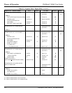
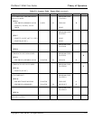
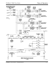
5.5 Pneumatic System
When reading about the pneumatic system, refer to
the 800rf Pneumatic Diagram on the next page.
The main feature of the pneumatic system used in the
800rf case sealer is that all of the directional control
valves are solenoid-operated. Each solenoid receives
operating voltages of either +24 VDC to energize it
or 0 VDC to de-energize it. These voltages come
from the Programmable Logic Controller (PLC)
located in the Electrical Control Panel. Whenever a
controller output is active
(at +24 VDC), an output-associated light emitting
diode (LED) lights to show that the solenoid is
energized and the valve is active.
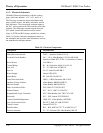
Valves V0 through V11 are 5-way, 2-position valves.
Facility compressed air of 95 100 PSIG minimum is
applied to the air fitting on the front of the case sealer
near the exit end. An Air On/Off Valve controls the
air supply to the case sealer. The air is filtered and
then regulated to 95 100 PSIG. Air from the Filter/
Regulator is supplied to port P of the Main Air valve
V0. From port A of V0, air is supplied to the main
manifold, the Air Indicator, the Counter-Balance
Pressure Regulator, Box Centering Pressure Regula-
tor, Side Belt Pressure Regulator, and the Paddle
Pressure Regulator. The air indicator shows red to
indicate that the air supply is on.
At the Head Brakes valve V1, air is supplied to port P
and through the valve to blocked port B. The spring
loaded head brakes remain on.
At the Side Drive Locks valve V2, air is supplied to
port P and through the valve to blocked port B. The
side drive assembly locks remain unlocked.
Air is supplied through the Head Lower Ports valve
V3 to the cap ends of the Head Assembly Cylinders.
At the same time, air is supplied from the Counter-
Balance Pressure Regulator through the Head Upper
Ports valve V4 to the rod ends of the cylinders. Since
both ends of the cylinders have pressure and the
brakes are on, the upper head assembly stays locked
in the up position.
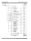
At the Centering Rails valve V5, air is supplied from
the Box Centering Pressure Regulator through the
valve to the rod end of the Centering Rails Cylinder
causing it to retract. The centering rails move out.
At the Side Drive Belts valve V6, air is supplied from
the Side Belt Pressure Regulator through the valve to
the rod end of the Side Drive Belts Cylinder causing
it to retract. The side drive belts move out.
At the Paddle valve V7, air is supplied from the
Paddle Pressure Regulator through the valve to the
rod end of the Paddle Cylinder causing it to retract.
The paddle moves down.
At the Infeed Gate valve V8, air is supplied from the
manifold through the valve to the cap end of the
Infeed Gate Cylinder causing it to extend. The infeed
gate moves up.
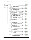
At the Flap Folder Arm valve V9, air is supplied from
the manifold through the valve to the cap end of the
Flap Folder Arm Cylinder causing it to extend. The
flap folder arm moves up.
At the Rear Flap Folder valve V10, air is supplied
from the manifold through the valve to the cap end of
the Rear Flap Folder Cylinder causing it to extend.
The rear flap folder itself is retracted back into the
flap folder arm.
At the Fork valve V11, air is supplied from the
manifold through the valve to the rod end of the Fork
Cylinder causing it to retract. The fork moves down.
ü Note
Valves V1 through V11 can be manually actuated to
initiate the operation of other pneumatic components
within the 800rf case sealer. Refer to Pneumatic
Component Testing in Section 6, Troubleshooting.