Theory of Operation 3M-Matic 800rf Case Sealer
5-14 Copyright 1999, 3M IPC. All rights reserved.
5-4. Electrical System
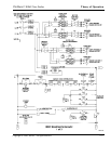
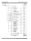
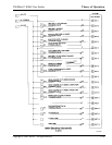
When reading about the electrical system, refer to the
800rf Electrical Schematic in Subsection 5-4-3.
5-4-1. Power Distribution
The Main Disconnect switch DISC 1 controls
3-phase, 208 240 VAC to the 800rf case sealer.
Turning DISC 1 ON applies 3-phase, 208 240 VAC
to the 1-3-5 contacts of the Overload Circuit Breakers
OL3 and OL4 which feed the 1-3-5 contacts of the
Motor Control Relays K2 and K4. These breakers
provide protection for the infeed drive motors. The
Infeed Drive Motors #1 and #2 do not receive power
until later, when the controller energizes Motor
Control Relays K2 (PLC OUT 3) and K4
(PLC OUT 12).
Turning DISC 1 ON also applies 3-phase, 208 240
VAC to the 1-3-5 contacts of the Motor Control Relay
K1 which feeds the 1-3-5 contacts of the Overload
Circuit Breakers OL1 and OL2. These breakers
provide protection for the side belt drive motors,
which do not receive power until later when the
controller energizes Motor Control Relay K1
(PLC OUT 1).
Single-phase, 208 240 VAC is applied to the Omron
power supply. The power supply output is +24 VDC
which is used to energize the POWER lamp and
supply power to terminal VDC 4 on the PLC, the
Guard Door Interlocks GRD1, GRD2, GRD3, and
GRD4, the rear and front E-Stop switches, and
auxiliary contacts of the Overload Circuit Breakers
OL1, OL2, OL3, and OL4.
The POWER lamp, located on the Electrical Control
Panel, lights to show that +24 VDC is present.
Pressing the RESET switch energizes the Master
Control Relay K3 which provides +24 VDC power
for operation of all photocells and reed switches, the
Main Air Solenoid SV0, and terminals VDC 1, VDC
2, and VDC 3 on the PLC
In addition, +24 VDC is used as direct signal input to
the controller via the STOP switch (PLC IN 0),
START switch (PLC IN 1), RESET switch (PLC IN
2), E-Stop/Guard Door switches (PLC IN 3), FIXED
mode switch (PLC IN 13), BYPASS mode switch
(PLC IN 14), Low Air Pressure switch SU2 (PLC IN
15), and the Overload Circuit Breakers OL1, OL2,
OL3, and OL4 (PLC IN 17).
The ALARM BEACON (top of machine) and FAULT
lamp (Electrical Control Panel) light when the
controller detects a machine error and energizes
Alarm Relay K5 (PLC OUT 13).
5-4-2. Special Circuits/Components
Programmable Logic Controller
The Allen-Bradley SLC 500 contained in the
Model 800rf Type 39800 Case Sealer is a Program-
mable Logic Controller (PLC). A PLC processes
binary (one - zero, on - off, high - low) input signals
to produce output (control) signals which directly
influence electrical or mechanical processes, opera-
tions, or sequences.
In the 800rf, the PLC controls the drive motors and
all pneumatic components to ensure that all of the
steps in the case sealing sequence occur in the correct
order, with event timing coordinated with case length.
ü Note
Refer to the PLC Addendum at the back of this
manual for more PLC-related information.
Limit Switches
The limit switches used in the 800rf are air cylinder-
mounted, reed switches that are powered by +24
VDC. They magnetically sense the presence of the
cylinders internal piston base. When non-activated,
the limit switch output is low (0 V). When activated,
by the presence of the cylinder piston, the limit
switch output is high (+24 VDC)


