3M-Matic 800rf Case Sealer Installation
Copyright 1999, 3M IPC. All rights reserved. 2-21
2-8. Special Setup Procedure
2-8-1. Relocating Pneumatic and Electrical
Control Panels
Turn off electrical power and air supply and
disconnect power cord from electrical
supply before beginning this procedure.
Failure to comply with these warnings can
result in severe personal injury and/or
equipment damage.
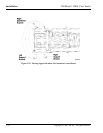
Relocating the case sealer Pneumatic and Electrical
Control Panels from their standard position which is
the left/front side, as viewed from the infeed end of
the machine, enables the case sealer to be operated
from the right/rear side of the machine.
At various steps of this procedure it is recommended
that two (2) people be involved in moving certain
components from the front to the rear of the case
sealer.
To prevent the case sealer from rolling, lock all the
casters before starting these procedures.
ü Note
Following these procedures will accomplish having
the control panels located to the right/rear of the case
sealer and will orient the Electrical Control Panel on
the left and the Pneumatic Control Panel on the right,
as viewed by the operator facing the rear side of the
machine.
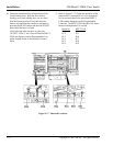
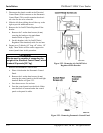
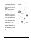
Removing Air On/Off Valve/Regulator/Filter,
Pneumatic Control Panel, and Brackets
1. Disconnect the air supply from the Air On/Off
Valve.
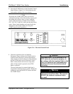
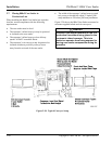
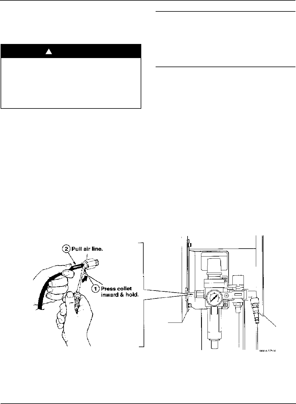
2. Open the Pneumatic Control Panel (use 8 mm hex
wrench) to assist in removing the input air line
from the air outlet on the Main Air Pressure
Regulator. Push in and hold the collet (release
ring) and pull the air line free. Refer to
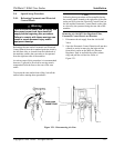
Figure 2-21.
Figure 2-21. Disconnecting Air Line
Warning!


