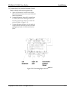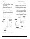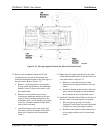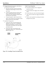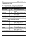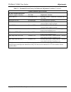
Table 3-1. Pneumatic Device Factory Set Points and Adjustment Locations (Continued)
Cylinder Mounted Speed Controls
Air Rate Exhaust Restriction
Controls (Speed Controls) Set Value Adjustment Location
Infeed Gate UP 3/4 of turn CCW On Gate Cylinder Underside of entrance end of
case sealer
Infeed Gate DOWN Not applicable No control device is present
Fork UP 12 turns CCW On Fork Cylinder cap end Remove center
conveyor bed to expose cylinder
Fork DOWN 13 turns CCW On Fork Cylinder rod end Remove center
conveyor bed to expose cylinder
Folder Arm EXTEND 11 turns CCW On Folder Arm Cylinder rod end Through access
holes in Arm Assembly cover
Folder Arm RETRACT 5 turns CCW On Folder Arm Cylinder cap end Through access
holes in Arm Assembly cover
Rear Flap Folder EXTEND 16 turns CCW On Rear Flap Folder Cylinder rod end Through
access holes in Folder Assembly cover
Rear Flap Folder RETRACT 10 turns CCW On Rear Flap Folder Cylinder cap end Through
access holes in Folder Assembly cover
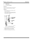
All adjustments are made from the fully closed position. Use a standard straight edge screwdriver or loosen the
knurled ring nut and adjust the thumbscrew fully CW, then turn the thumbscrew CCW the number of turns
specified above.
3M-Matic 800rf Case Sealer Adjustments
Copyright 1999, 3M IPC. All rights reserved. 3-3


