


3M-Matic 800rf Case Sealer Illustrated Parts Breakdown
Copyright 1999, 3M IPC. All rights reserved. 7-i
Table of Contents
7. Illustrated Parts Breakdown........................................................................................................................ 7-1
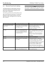
7-1.How to Order Replacement Parts ............................................................................................................. 7-1
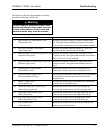
7-2.Spare Parts ................................................................................................................................................ 7-1
7-3.Suggested Spare Parts .............................................................................................................................. 7-1
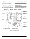
7-4.Illustrations and Parts Lists ...................................................................................................................... 7-2
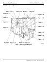
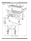
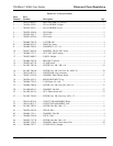
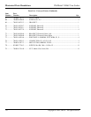
Figure 7-1. 800rf Case Sealer Breakdown ................................................................................. 7-2
Figure 7-2. Conveyor Frame ...................................................................................................... 7-4
Figure 7-3. Conveyor Center Bed and Fork ............................................................................... 7-8
Figure 7-4. Conveyor Bed Rollers ........................................................................................... 7-10
Figure 7-5. Side Belt Centering................................................................................................ 7-12
Figure 7-6. Column Assembly.................................................................................................. 7-16
Figure 7-7. Flap Folder Assembly ............................................................................................ 7-18
Figure 7-8. Paddle Assembly.................................................................................................... 7-22
Figure 7-9. Side Belt Rail Assembly ........................................................................................ 7-24
Figure 7-10. Head Cylinder Assembly ..................................................................................... 7-26
Figure 7-11. Upper Tape Head Mount...................................................................................... 7-28
Figure 7-12. Upper Tape Drum Bracket Assembly .................................................................. 7-30
Figure 7-13. Side Belt and Drive Assemblies .......................................................................... 7-32
Figure 7-14. Side Belt Drive Pulleys (Detail) ..........................................................................7-36
Figure 7-15. Upper Head Conduit Assembly ........................................................................... 7-38
Figure 7-16. Electrical Control Panel....................................................................................... 7-40
Figure 7-17. Electrical Control Panel (Detail) ......................................................................... 7-44
Figure 7-18. Pneumatic Control Panel .....................................................................................7-46
Figure 7-19. Pneumatic Components, #1 ................................................................................. 7-48
Figure 7-20. Pneumatic Components, #2 ................................................................................. 7-50
Figure 7-21. Pneumatic Components, #3 ................................................................................. 7-52
Figure 7-22. Sliding Door Assembly ........................................................................................7-56
Figure 7-23. Infeed Conveyor Frame ....................................................................................... 7-60
Figure 7-24. Infeed Conveyor Drive Assembly........................................................................ 7-64
Figure 7-25. Infeed Conveyor Centering Assembly ................................................................. 7-66
Figure 7-26. Taping Head Assemblies - AccuGlide II STD 2-Inch ...................................... 7-70
Figure 7-27. Frame Assembly for Upper Head ........................................................................ 7-72