


Disassembly/Reassembly 3M-Matic 800rf Case Sealer
4-12 3M 1998 December
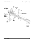
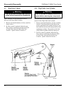
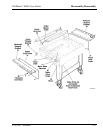
4-14. Infeed Rollers
1. Remove the photocell connectors [40] from
photocells PC1 and PC2.
2. Remove the front photocell support bracket [34]
secured by 3 hex-head screws.
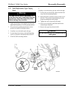
3. Remove the Infeed front side cover [31] exposing
the roller drive chain [25], roller sprockets [23],
motor drive sprocket [11], and roller flanged
bearings [15].
4. Remove the rear photocell reflector support
bracket [34] secured by 3 hex-head screws.
5. Remove the Infeed rear side cover [31] exposing
the roller drive chain [25], roller sprockets [23],
motor drive sprocket [11], and roller flanged
bearings [15].
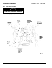
6. Loosen, but do not remove, the four (4) motor
positioning hex-head bolts.
7. Move the motor [26] upward providing slack in
the chain [25].
8. Tighten the motor bolts to hold the motor in this
position.
9. Remove the chain slide [13].
10. If the chain has enough slack, slip it over the
motor drive sprocket [11]. If the chain does not
have enough slack, locate and remove the master
chain link and remove the chain.
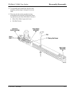
11. Identify the roller you are replacing and remove
the roller sprocket [23] secured by a hex screw at
the keyway.
12. Remove the front and rear roller flanged bearings
[15] secured by three (3) hex-head screws each.
13. Loosen the roller spacer collars located on the
roller shafts at each end of the roller. Each collar
is secured by (2) set screws. Loosen the set
screws until the collars turn freely.
14. Slide the roller shaft to the left through the hole
created by the bearing removal. Then, lift the
right side of the roller up and out of the Infeed
frame.
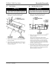
15. Install the new roller by following the reverse
order of the disassembly procedure.
ü Note
Be sure to align the drive chain. Install the chain
taunt around all roller and drive sprockets. Do this
by loosening the four (4) motor bolts, moving the
motor downward until the chain is taunt with no
slack, and then tightening the bolts. Also, be careful
when inserting the photocell electrical connectors.
Notice that the 4-pin connectors are keyed for proper
pin positioning.