3M-Matic 800rf Case Sealer Installation
Copyright 1999, 3M IPC. All rights reserved. 2-17
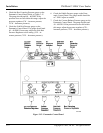
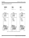
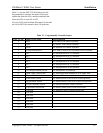
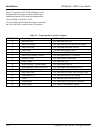
Table 2-1 lists the INPUT LEDs displayed on the
Programmable Controller, the names of the input
signals that feed the LEDs, and the conditions that
cause the LEDs to turn ON or OFF.
View the LEDs with the Main Disconnect Switch and
the Air On/Off Valve turned to their ON positions.
Table 2-1. Programmable Controller Inputs
INPUT LED Input Signal Name LED Condition
0 Stop OFF when STOP button is pushed.
1 Start ON when START button is pushed.
2 Reset ON when RESET button is pushed.
3 E-Stop/Sliding Door OFF when E-Stop switch is pushed or door is opened.
4 PC1 ON when photocell PC1 is blocked.
5 PC2 ON when photocell PC2 is blocked.
6 PC3 ON when photocell PC3 is blocked.
7 PC4 ON when photocell PC4 is blocked.
8 PC5 ON when photocell PC5 is blocked.
9 PC6 ON when photocell PC6 is blocked.
10 Box Height (Paddle) Switch ON when paddle is pushed up.
11 Head Upper Limit Switch ON when upper head assembly is at its upper limit.
12 Minimum Width Switch ON when side belt assemblies close to innermost position.
13 Fixed Mode Switch ON when selector switch is set to FIXED position.
14 Bypass Mode Switch ON when selector switch is set to BYPASS position.
15 Low Air Pressure Switch ON when air pressure is above 50 PSIG.
16 Flap Folder Arm Switch ON when cylinder piston is near reed switch.
17 Overload ON when any motor overload switch trips.
18 Not used
19 Not used
20 Not used
21 Not used
22 Not used
23 Not used


