3M-Matic 800rf Case Sealer Installation
Copyright 1999, 3M IPC. All rights reserved. 2-11
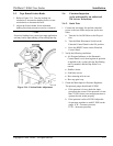
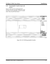
2-5. Tape Drum Friction Brake
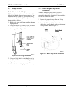
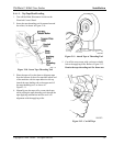
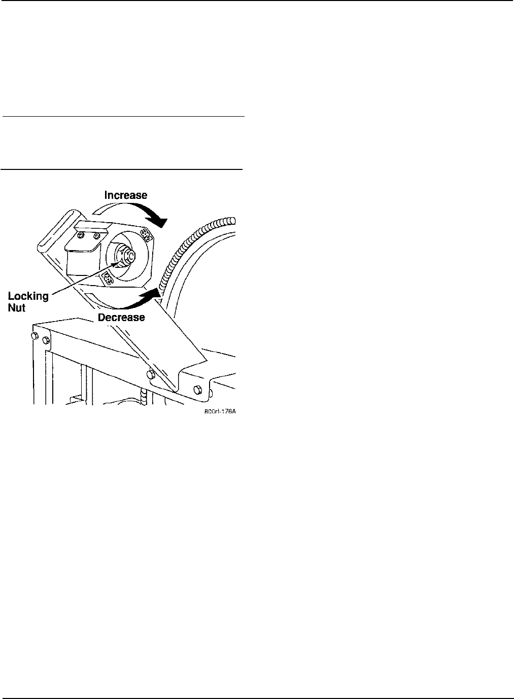
1. Refer to Figure 2-14. Turn the locking nut
clockwise to increase the braking force or coun-
terclockwise to decrease the force.
2. Adjust the friction brake for the minimum
braking force that prevents excessive overtravel.
ü Note
Excessive braking force causes poor tape application
and may lead to tape tabbing on the trailing tape leg.
Figure 2-14. Friction Brake Adjustment
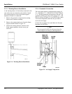
2-6. Checkout Inspection
(to be performed by an authorized
3M Service Technician)
2-6-2. Static Tests
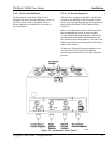
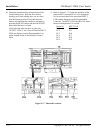
1. Connect the air supply line and the electrical
power to the case sealer and power up the ma-
chine.
a. Turn the Air On/Off Valve to the ON posi-
tion.
b. Turn the Main Disconnect Switch on the
Electrical Control Panel to the ON position.
c. Press the RESET button on the Electrical
Control Panel.
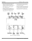
2. Verify the following conditions:
• Air Pressure Indicator on the Pneumatic
Control Panel is red, showing that air pressure
is applied to the system, the rear flap folding
arm is extended, and the flap folder is re-
tracted.
• Paddle is down.
• Side belts are out.
• Box centering rails are out.
• Box stop gate is up.
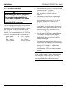
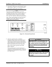
3. Check the Main Input Air Pressure Regulator.
The pressure gauge should read 95 PSIG.
a. If the pressure is lower, check the input
pressure at the source. If the pressure is lower
than 75 PSIG, there is not enough pressure to
operate the case sealer properly.
b. If the pressure is above 95 PSIG, adjust the
air pressure regulator to read 95 PSIG on the
gauge. (CW increases pressure,
CCW decreases pressure).


