


3M-Matic 800rf Case Sealer Theory of Operation
Copyright 1999, 3M IPC. All rights reserved. 5-1
5. Theory of Operation
5-1. General
This section begins with an operation summary,
which gives an overview of the operations that the
Model 800rf Type 39800 Case Sealer performs as it
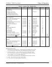
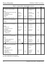
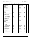
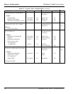
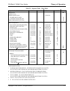
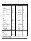
seals a carton. Next, the sequence tables provide a
detailed sequence of actions the case sealer performs
while operating in Random mode, Fixed mode, or
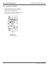
Bypass mode. Then, the electrical system is de-
scribed, including special circuits and components.
The section ends with a description of the pneumatic
system.
5-2. Operation Summary
The 800rf case sealer runs in three separate modes of
operation: Random, Fixed, and Bypass. These
operating modes are described in the following
subsections.
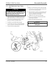
5-2-1. Random Mode
When a box enters and passes through the case sealer,
it passes six photocells in sequence. As the box clears
the light path of the first photocell, the infeed gate
moves up to prevent the entry of the next box. A pair
of centering rails then move inward to center the box
on the infeed rollers.
Infeed drive rollers move the box past a second
photocell which senses the presence of the box to
subsequently control the timing of the side belt
restart circuit.
The box continues to move, blocking the light path of
the third photocell. This causes the side belt drive
assemblies to move inward and press against the sides
of the box. The counter adds 1 to the cycle count, and
the box is carried forward, blocking the light path of
the fourth photocell. The side belt drive motors turn
off, and the box stops at the fork beneath the head
assembly.
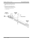
When the box blocks the light path of the fourth
photocell, the side belt drive assemblies lock in
position, the upper head assembly brakes unlock, and
the head assembly begins to move downward. This
downward movement continues until a paddle presses
against the front flap of the box, folding the flap
inward. Downward movement of the head assembly
continues until resistance of the box leading edge
moves the paddle upward, actuating the box height
limit switch. An output from the controller stops
downward movement of the head assembly. At this
time, the head assembly and paddle lock in position,
the fork moves down, and the rear flap-folding
process occurs.
Rear flap folding begins with the action of the flap
folder arm. As this arm moves downward, an associ-
ated limit switch actuates an output from the control-
ler which causes the rear flap folder to move down,
folding the rear flap of the box inward.
The timing for the side belt drive motors to start
depends on whether the box is short or long. For a
short box (second photocell not blocked), the drive
motors are delayed momentarily to allow the rear flap
to be folded and then the motors turn on. For a long
box (second photocell blocked), the side belt drive
motors turn on first and then the rear flap is folded
when the box clears the second photocell.
The side belt drive assemblies move the box toward
the taping heads. As the box moves forward, the side
flaps are folded inward and then held in position by
compression rollers. The box passes between the
taping heads and a C-clip of tape is applied to the top
and bottom center seams of the box.
As the box exits the case sealer, it clears the light
path of the fifth photocell and the controller homes
the case sealer, preparing it for the next box. At this
time, the flap folder arm and rear flap folder move up,
the side belt drive assemblies move out, the paddle
moves down, and the upper head assembly raises and
locks in the up position.