102
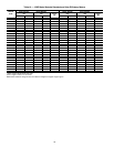
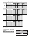
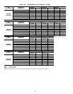
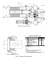
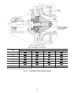
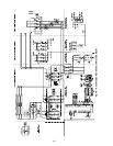
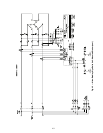
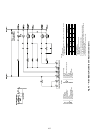
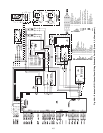
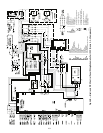
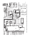
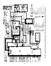
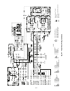
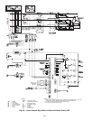
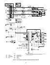
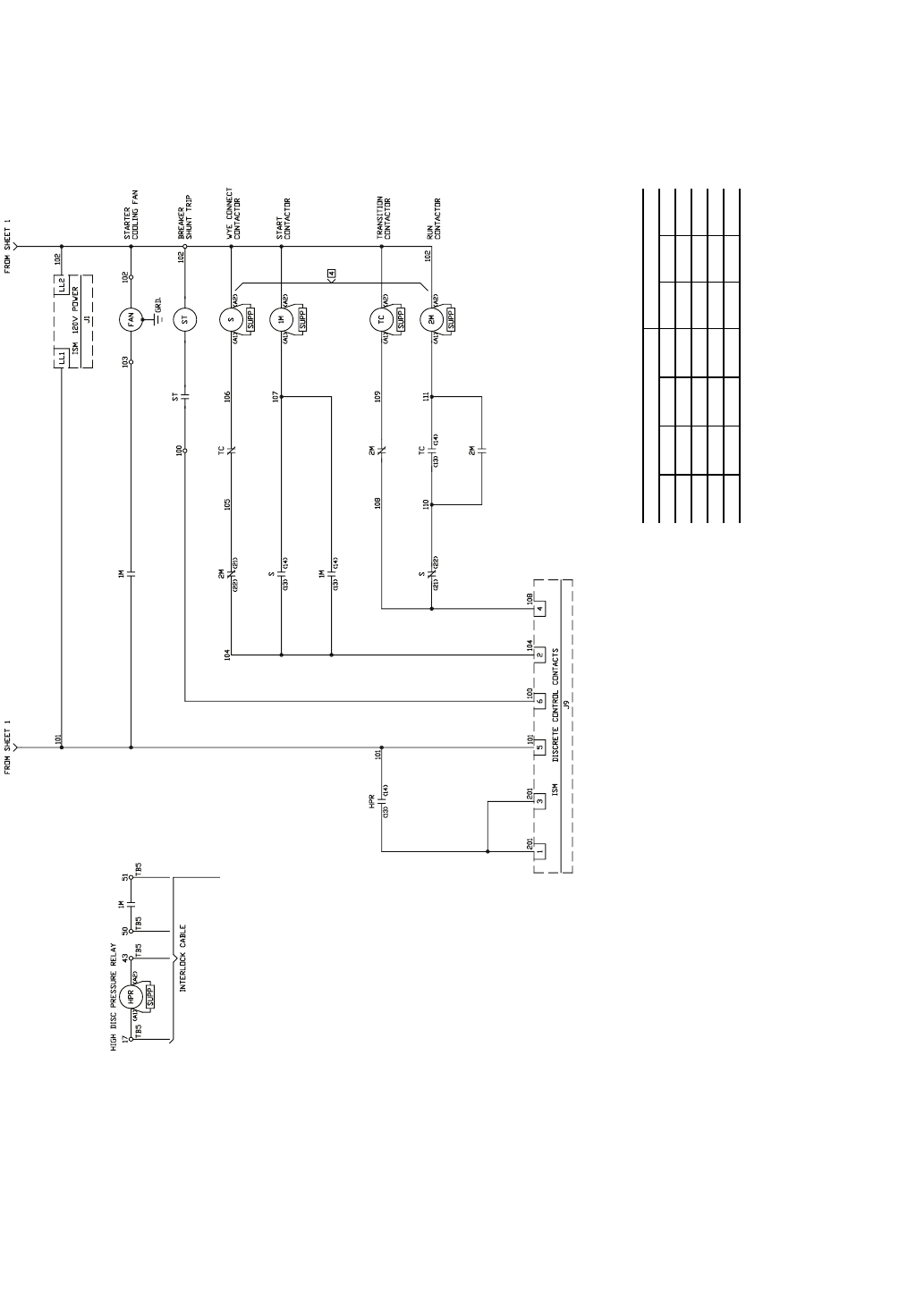
Fig. 45 — Allen-Bradley Wye-Delta Unit-Mounted Starter (cont)
C — Contactor
CB — Circuit Breaker
CP — Control Power
CT — Current Transformer
DS — Disconnect Switch
FU — Fuse
GRD — Ground
HPR — High Pressure Relay
ISM — Integrated Starter Module
L — Main Supply Power
LL — Control Power Supply
M — Contactor
OP — Oil Pump
PFCC — Power Factor Correction Capacitor
RES — Resistor
S — Contactor
ST — Shunt Trip
TB — Terminal Block
TC — Transition Contactor
VL — Wire Label
LEGEND
NOTES:
1. Remote device.
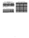
2. Transformer connected for 480 v primary 120 v secondary. For other
voltages see chart:
3. Current transformer
•amps nameplate ratio
•amps effective ratio with primary turns
•polarity marking
Be sure to connect per polarity markings.
4. “S” - “2M” contactors are electrically and mechanically interlocked.
5. Live capacitor unit. Deenergize starter. Wait one (1) minute and ground
terminals before servicing.
6. All control wiring 14 gage red except as noted.
PRIMARY SECONDARY
H1-H2 H1-H3 H1-H4 H1-H5 X1-X2 X1-X3 X1-X4
240 416 480 600 99 120 130
230 400 460 575 95 115 125
220 380 440 550 91 110 120
208 500 85 100 110


