


33
PIC II System Functions
NOTE: Words not part of paragraph headings and printed in all
capital letters can be viewed on the CVC/ICVC (e.g., LOCAL,
CCN, RUNNING, ALARM, etc.). Words printed both in all
capital letters and italics can also be viewed on the CVC/ICVC
and are parameters (CONTROL MODE, TARGET GUIDE
VANE POS, etc.) with associated values (e.g., modes, tempera-
tures, pressures, percentages, on, off, enable, disable, etc.).
Words printed in all capital letters and in a box represent soft-
keys on the CVC/ICVC (e.g., and ). See
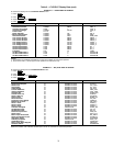
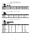
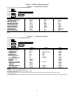
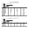
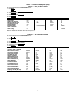
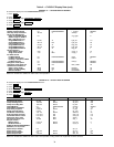
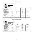
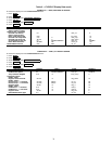
Table 2 for examples of the type of information that can appear
on the CVC/ICVC screens. Figures 14-20 give an overview of
CVC/ICVC operations and menus.
CAPACITY CONTROL FIXED SPEED — The PIC II con-
trols the chiller capacity by modulating the inlet guide vanes in
response to chilled water temperature deviation from the CON-
TROL POINT. The CONTROL POINT may be changed by a
CCN network device or is determined by the PIC II adding any
active chilled water reset to the SET POINT. The PIC II uses
the PROPORTIONAL INC (Increase) BAND, PROPOR-
TIONAL DEC (Decrease) BAND, and the PROPORTIONAL
ECW (Entering Chilled Water) GAIN to determine how fast or
slow to respond. CONTROL POINT may be viewed or over-
ridden from the MAINSTAT screen.
CAPACITY CONTROL VFD — The PIC II controls the
machine capacity by modulating the motor speed and inlet
guide vanes in response to chilled water temperature deviation
from the CONTROL POINT. The controller will maintain the
highest inlet guide vane setting at the lowest speed to maxi-
mize efficiency while avoiding surge. The CONTROL POINT
may be changed by a CCN network device or is determined by
the PIC II adding any active chilled water reset to the to the
SET POINT. CONTROL POINT may be viewed or overridden
from the MAINSTAT screen. The PIC II uses the PROPOR-
TIONAL INC (Increase) BAND, PROP DEC (Decrease)
BAND, and the PROPORTIONAL ECW (Entering Chilled
Water) GAIN to determine how fast or slow it takes the system
to respond. The VFD GAIN allows for additional adjustment of
the VFD response. At start-up, the inlet guide vanes (IGV)
start in the closed position and the VFD ramps to its minimum
speed setting.
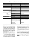
The PIC II controller then initiates the Capacity Control al-
gorithm to maintain the chilled water temperature at the CON-
TROL POINT. During operation when the CONTROL POINT
is not met, the controller will establish a GUIDE VANE DELTA
which will either affect a percentage change to the GUIDE
VANES or the VFD TARGET SPEED. Any change that will be
made to the IGV position or the VFD SPEED will depend on
whether the GUIDE VANE DELTA is positive or negative, and
the status of the Surge Control Algorithm. The Surge Control
Algorithm determines if the chiller should operate in Normal
Mode or Surge Prevention Mode. The logic for how the IGV’s
and VFD SPEED will be affected by the GUIDE VANE DEL-
TA and the Surge Control Algorithm can be seen below:
Normal Control mode occurs when ACTIVE DELTA T >
SURGE/HGBP DELTA T.
Surge Prevention Mode occurs when ACTIVE DELTA T
≤ SURGE/HGBP DELTA T.
The TARGET VFD SPEED, ACTUAL VFD SPEED and the
VFD GAIN can be viewed and modified in the CAPACITY
display screen. The TARGET VFD SPEED can be manually
overridden by the operator from the COMPRESS screen. The
VFD MINIMUM SPEED, MAXIMUM SPEED, VFD GAIN
and INCREASE STEP can be viewed and modified in the
SETUP2 display screen. TARGET and ACTUAL VFD SPEED
can be viewed in the COMPRESS screen.
ECW CONTROL OPTION — If this option is enabled, the
PIC II uses the ENTERING CHILLED WATER temperature to
modulate the vanes instead of the LEAVING CHILLED
WATER temperature. The ECW CONTROL OPTION may be
viewed on the TEMP_CTL screen, which is accessed from the
EQUIPMENT SERVICE screen.
CONTROL POINT DEADBAND — This is the tolerance
range on the chilled water/brine temperature control point. If
the water temperature goes outside the CHILLED WATER
DEADBAND, the PIC II opens or closes the guide vanes until
the temperature is within tolerance. The PIC II may be config-
ured with a 0.5 to 2 F (0.3 to 1.1 C) deadband. CHILLED
WATER DEADBAND may be viewed or modified on the
SETUP1 screen, which is accessed from the EQUIPMENT
SERVICE table.
For example, a 1° F (0.6° C) deadband setting controls the
water temperature within ±0.5° F (0.3° C) of the control point.
This may cause frequent guide vane movement if the chilled
water load fluctuates frequently. A value of 1° F (0.6° C) is the
default setting.
DIFFUSER CONTROL — On 19XR FRAME sizes 4 and
5 compressors equipped with a variable discharge diffuser, the
PIC II adjusts the diffuser actuator position (DIFFUSER
ACTUATOR on the COMPRESS screen) to correspond to the
actual guide vane position (ACTUAL GUIDE VANE POS on
the COMPRESS screen).
The diffuser control can be enabled or disabled from the
SETUP2 screen. See Table 2, Example 19. In addition, the dif-
fuser and guide vane load points may be viewed and modified
from this screen. These points must be correct for the compres-
sor size. The diffuser opening can be incremented from fully
open to completely closed. A 0% setting is fully open; a 100%
setting is completely closed. To obtain the proper settings for
Diffuser Control, contact a Carrier Engineering representative.
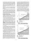
PROPORTIONAL BANDS AND GAIN — Proportional band
is the rate at which the guide vane position is corrected in pro-
portion to how far the chilled water/brine temperature is from
the control point. Proportional gain determines how quickly the
guide vanes react to how quickly the temperature is moving
from the CONTROL POINT. The proportional bands and gain
may be viewed or modified from the SETUP2 screen, which is
accessed from the EQUIPMENT SERVICE table.
The Proportional Band
— There are two response modes, one
for temperature response above the control point, the other for
the response below the control point.
The temperature response above the control point is called
the PROPORTIONAL INC BAND, and it can slow or quicken
guide vane response to chilled water/brine temperatures above
the DEADBAND. The PROPORTIONAL INC BAND can be
adjusted from a setting of 2 to 10; the default setting is 6.5.
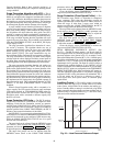
The response below the control point is called the PRO-
PORTIONAL DEC BAND, and it can slow or quicken the
guide vane response to chilled water temperature below the
deadband plus the control point. The PROPORTIONAL DEC
BAND can be adjusted on the CVC/ICVC from a setting of 2 to
10. The default setting is 6.0.
NOTE: Increasing either of these settings causes the guide
vanes to respond more slowly than they would at a lower
setting.
GUIDE VANE
DELTA
NORMAL
CONTROL
MODE
SURGE
PREVENTION
MODE
IGV VFD IGV VFD
From +0.2 to +2.0 1st 2nd 2nd 1st
From –0.2 to –2.0 2nd 1st 1st —
ENTER EXIT