


15
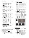
CVC/ICVC Operation and Menus (Fig. 14-20)
GENERAL
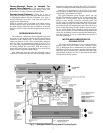
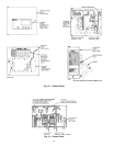
• The CVC/ICVC display automatically reverts to the
default screen after 15 minutes if no softkey activity
takes place and if the chiller is not in the pumpdown
mode (Fig. 14).
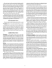
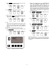
• If a screen other than the default screen is displayed on
the CVC/ICVC, the name of that screen is in the upper
right corner (Fig. 15).
• The CVC/ICVC may be set to display either English or
SI units. Use the CVC/ICVC configuration screen
(accessed from the Service menu) to change the units.
See the Service Operation section, page 45.
• Local Operation — The PIC II can be placed in local
operating mode by pressing the softkey. The
PIC II then accepts commands from the CVC/ICVC only
and uses the Local Time Schedule to determine chiller
start and stop times.
• CCN Operation — The PIC II can be placed in the CCN
operating mode by pressing the softkey. The PIC
II then accepts modifications from any CCN interface or
module (with the proper authority), as well as from the
CVC/ICVC. The PIC II uses the CCN time schedule to
determine start and stop times.
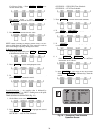
ALARMS AND ALERTS — An alarm shuts down the com-
pressor. An alert does not shut down the compressor, but it no-
tifies the operator that an unusual condition has occurred. An
alarm (*) or alert (!) is indicated on the STATUS screens on the
far right field of the CVC/ICVC display screen.
Alarms are indicated when the control center alarm light (!)
flashes. The primary alarm message is displayed on the default
screen. An additional, secondary message and troubleshooting
information are sent to the ALARM HISTORY table.
When an alarm is detected, the CVC/ICVC default screen
will freeze (stop updating) at the time of alarm. The freeze en-
ables the operator to view the chiller conditions at the time of
alarm. The STATUS tables will show the updated information.
Once all alarms have been cleared (by pressing the
softkey), the default CVC/ICVC screen will return to normal
operation.
CVC/ICVC MENU ITEMS — To perform any of the opera-
tions described below, the PIC II must be powered up and have
successfully completed its self test. The self test takes place au-
tomatically, after power-up.
Press the softkey to view the list of menu struc-
tures: , , , and
.
• The STATUS menu allows viewing and limited calibra-
tion or modification of control points and sensors, relays
and contacts, and the options board.
• The SCHEDULE menu allows viewing and modification
of the local and CCN time schedules and Ice Build time
schedules.
• The SETPOINT menu allows set point adjustments, such
as the entering chilled water and leaving chilled water set
points.
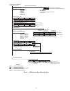
• The SERVICE menu can be used to view or modify
information on the Alarm History, Control Test, Control
Algorithm Status, Equipment Configuration, ISM Starter
Configuration data, Equipment Service, Time and Date,
Attach to Network Device, Log Out of Network Device,
and CVC/ICVC Configuration screens.
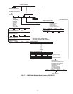
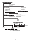
For more information on the menu structures, refer to
Fig. 17.
Press the softkey that corresponds to the menu structure to
be viewed: , , or
. To view or change parameters within any of these
menu structures, use the and softkeys
to scroll down to the desired item or table. Use the
softkey to select that item. The softkey choices that then appear
depend on the selected table or menu. The softkey choices and
their functions are described below.
BASIC CVC/ICVC OPERATIONS (Using the Soft-
keys) — To perform any of the operations described below,
the PIC II must be powered up and have successfully complet-
ed its self test.
LOCAL
CCN
RESET
MENU
STATUS SCHEDULE SETPOINT
SERVICE
STATUS SCHEDULE SETPOINT
SERVICE
NEXT PREVIOUS
SELECT
RUNNING TEMP CONTROL
LEAVING CHILLED WATER
01-01-95 11:48
28.8 HOURS
CHW IN CHW OUT EVAP REF
CDW IN CDW OUT COND REF
OIL PRESS OIL TEMP AMPS %
CCN LOCAL RESET MENU
55.1 44.1 40.7
85.0 95.0 98.1
21.8 132.9 93
PRIMARY STATUS
MESSAGE
COMPRESSOR
ON TIME
DATE TIME
SOFT KEYS
MENU
LINE
EACH KEY'S FUNCTION IS
DEFINED BY THE MENU DESCRIPTION
ON MENU LINE ABOVE
ALARM LIGHT
(ILLUMINATED
WHEN POWER ON)
STOP BUTTON
•
HOLD FOR ONE
SECOND TO STOP
•
•
BLINKS CONTINUOUSLY
ON FOR AN ALARM
BLINKS ONCE TO
CONFIRM A STOP
SECONDARY
STATUS
MESSAGE
CONTROL TEST
CONTROL ALGORITHM STATUS
EQUIPMENT CONFIGURATION
ISM (STARTER) CONFIGURATION DATA
EQUIPMENT SERVICE
TIME AND DATE
ATTACH TO NETWORK DEVICE
LOG OUT OF DEVICE
CVC CONFIGURATION
ALARM HISTORY
19XR_II
SERVICE
Fig. 15 — CVC/ICVC Service Screen
Fig. 14 — CVC/ICVC Default Screen