


35
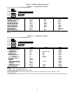
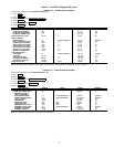
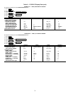
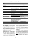
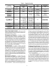
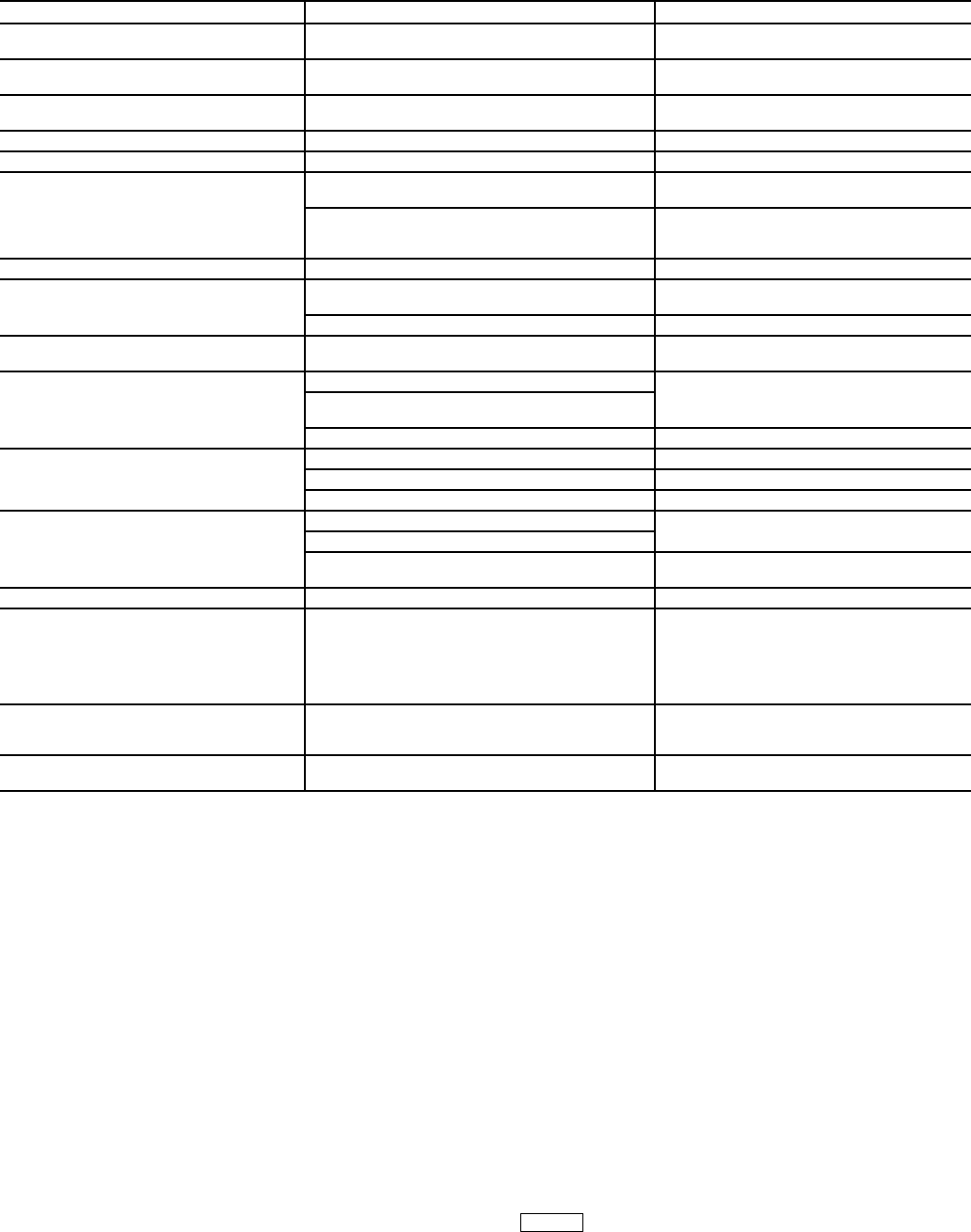
Table 3 — Protective Safety Limits and Control Settings
Shunt Trip (Option) —
The function of the shunt trip
option on the PIC II is to act as a safety trip. The shunt trip is
wired from an output on the ISM to a shunt trip equipped mo-
tor circuit breaker. If the PIC II tries to shut down the compres-
sor using a normal shutdown procedure but is unsuccessful for
20 seconds, the shunt trip output is energized and causes the
circuit breaker to trip off. If ground fault protection has been
applied to the starter, the ground fault trip also energizes the
shunt trip to trip the circuit breaker. Protective devices in the
starter can also energize the shunt trip. The shunt trip feature
can be tested using the Control Test feature.
Default Screen Freeze —
When the chiller is in an
alarm state, the default CVC/ICVC display “freezes,” that is, it
stops updating. The first line of the CVC/ICVC default screen
displays a primary alarm message; the second line displays a
secondary alarm message.
The CVC/ICVC default screen freezes to enable the opera-
tor to see the conditions of the chiller at the time of the alarm. If
the value in alarm is one normally displayed on the default
screen, it flashes between normal and reverse video. The CVC/
ICVC default screen remains frozen until the condition that
caused the alarm is remedied by the operator. Use CVC/ICVC
display and alarm shutdown record sheet (CL-13) to record all
values from default screen freeze.
Knowledge of the operating state of the chiller at the time an
alarm occurs is useful when troubleshooting. Additional chiller
information can be viewed on the status screens and the
ISM_HIST screen. Troubleshooting information is recorded in
the ALARM HISTORY table, which can be accessed from the
SERVICE menu.
To determine what caused the alarm, the operator should
read both the primary and secondary default screen messages,
as well as the alarm history. The primary message indicates the
most recent alarm condition. The secondary message gives
more detail on the alarm condition. Since there may be more
than one alarm condition, another alarm message may appear
after the first condition is cleared. Check the ALARM HISTO-
RY screen for additional help in determining the reasons for the
alarms. Once all existing alarms are cleared (by pressing the
softkey), the default CVC/ICVC display returns to
normal operation.
MONITORED PARAMETER LIMIT APPLICABLE COMMENTS
TEMPERATURE SENSORS OUT OF
RANGE
–40 to 245 F (–40 to 118.3 C) Must be outside range for 2 seconds
PRESSURE TRANSDUCERS OUT OF
RANGE
0.06 to 0.98 Voltage Ratio Must be outside range for 3 seconds.
Ratio = Input Voltage ÷ Voltage Reference
COMPRESSOR DISCHARGE
TEMPERATURE
>220 F (104.4 C) Preset, alert setting configurable
MOTOR WINDING TEMPERATURE >220 F (104.4 C) Preset, alert setting configurable
BEARING TEMPERATURE >185 F (85 C) Preset, alert setting configurable
EVAPORATOR REFRIGERANT
TEMPERATURE
<33 F (for water chilling) (0.6°C) Preset, configurable chilled medium for water
(SETUP1 table)
<EVAP REFRIG TRIPPOINT (set point adjustable
from 0 to 40 F [–18 to 4 C]) for brine chilling)
Configure chilled medium for brine (SETUP1
table). Adjust EVAP REFRIG TRIPPOINT for
proper cutout
TRANSDUCER VOLTAGE <4.5 vdc> 5.5 vdc Preset
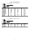
CONDENSER PRESSURE — SWITCH 165 ± 5 psig (1138 ± 34 kPa), reset at
110 ± 7 psig (758 ± 48 kPa)
Preset
— CONTROL 165 psig (1138 kPa) Preset
OIL PRESSURE Cutout <15 psid (103 kPad)
Alert <18 psid (124 kPad)
Preset
LINE VOLTAGE — HIGH >150% for one second or >115% for ten seconds Preset, based on transformed line voltage
to ISM. Also monitored at CVC/ICVC and
CCM power input.
— LOW <85% for ten seconds or ≤80 for 5 seconds or
<75% for one second
— SINGLE-CYCLE <50% for one cycle (if enabled) Default is disabled.
COMPRESSOR MOTOR LOAD >110% for 30 seconds Preset
<15% with compressor running Preset
>15% with compressor off Preset
STARTER ACCELERATION TIME
(Determined by inrush current)
150% RLA for 20 sec. For chillers with reduced voltage mechanical
and solid-state starters
>100% RLA for 45 sec.
>100% RLA for 10 sec. For chillers with full voltage starters
(Configures on ISM_CONF table).
STARTER TRANSITION If ISM contact open >20 sec. Reduced voltage starters only
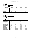
CONDENSER FREEZE PROTECTION Energizes condenser pump relay if
condenser refrigerant temperature or condenser
entering water temperature is below the configured
condenser freeze point temperature. Deenergizes
when the temperature is 5 F (3 C) above con-
denser freeze point temperature.
CONDENSER FREEZE POINT configured in
SETUP1 table with a default setting of 34 F
(1 C).
DISCHARGE SUPERHEAT Minimum value calculated based on
operating conditions and then compared
to actual superheat.
Calculated minimum required superheat
and actual superheat are shown on
OVERRIDE screen.
VARIABLE DIFFUSER OPERATION Detects discharge pulses caused by
incorrect diffuser position.
Preset, no calibration needed.
RESET