


72
TESTING WITH REFRIGERANT TRACER — Use an en-
vironmentally acceptable refrigerant as a tracer for leak test
procedures. Use dry nitrogen to raise the machine pressure to
leak testing levels.
TESTING WITHOUT REFRIGERANT TRACER — An-
other method of leak testing is to pressurize with nitrogen only
and to use a soap bubble solution or an ultrasonic leak detector
to determine if leaks are present.
TO PRESSURIZE WITH DRY NITROGEN
NOTE: Pressurizing with dry nitrogen for leak testing should
not be done if the full refrigerant charge is in the vessel
because purging the nitrogen is very difficult.
1. Connect a copper tube from the pressure regulator on the
cylinder to the refrigerant charging valve. Never apply
full cylinder pressure to the pressurizing line. Follow the
listed sequence.
2. Open the charging valve fully.
3. Slowly open the cylinder regulating valve.
4. Observe the pressure gage on the chiller and close the
regulating valve when the pressure reaches test level. Do
not exceed 140 psig (965 kPa).
5. Close the charging valve on the chiller. Remove the cop-
per tube if it is no longer required.
Repair the Leak, Retest, and Apply Standing
Vacuum Test —
After pressurizing the chiller, test for
leaks with an electronic halide leak detector, soap bubble solu-
tion, or an ultrasonic leak detector. Bring the chiller back to at-
mospheric pressure, repair any leaks found, and retest.
After retesting and finding no leaks, apply a standing vacu-
um test. Then dehydrate the chiller. Refer to the Standing Vacu-
um Test and Chiller Dehydration section (pages 50 and 53) in
the Before Initial Start-Up section.
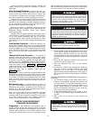
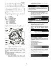
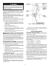
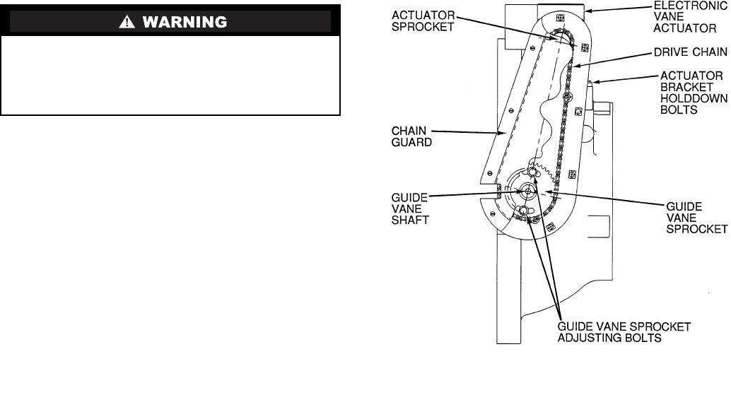
Checking Guide Vane Linkage —
When the chiller
is off, the guide vanes are closed and the actuator mechanism is
in the position shown in Fig. 37. If slack develops in the drive
chain, do the following to eliminate backlash:
1. With the chiller shut down and the actuator fully closed,
remove the chain guard and loosen the actuator bracket
hold-down bolts.
2. Loosen guide vane sprocket adjusting bolts.
3. Pry bracket upwards to remove slack, then retighten the
bracket hold-down bolts.
4. Retighten the guide vane sprocket adjusting bolts. Ensure
that the guide vane shaft is rotated fully in the clockwise
direction in order close it fully.
Trim Refrigerant Charge —
If, to obtain optimal chill-
er performance, it becomes necessary to adjust the refrigerant
charge, operate the chiller at design load and then add or re-
move refrigerant slowly until the difference between the leav-
ing chilled water temperature and the cooler refrigerant tem-
perature reaches design conditions or becomes a minimum. Do
not overcharge.
Refrigerant may be added either through the storage tank or
directly into the chiller as described in the Charge Refrigerant
into Chiller section.
To remove any excess refrigerant, follow the procedure in
Transfer Refrigerant from Chiller to Pumpout Storage Tank
section, Steps 1a and b, page 70.
WEEKLY MAINTENANCE
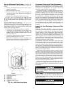
Check the Lubrication System —
Mark the oil lev-
el on the reservoir sight glass, and observe the level each week
while the chiller is shut down.
If the level goes below the lower sight glass, check the oil
reclaim system for proper operation. If additional oil is re-
quired, add it through the oil drain charging valve (Fig. 2). A
pump is required when adding oil against refrigerant pressure.
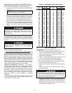
The oil charge for the 19XR compressor depends on the com-
pressor Frame size:
• Frame 2 compressor — 5 gal (18.9 L)
• Frame 3 compressor — 8 gal (30 L)
• Frame 4 compressor — 10 gal (37.8 L)
• Frame 5 compressor — 18 gal (67.8 L)
The added oil must meet Carrier specifications for the
19XR. Refer to Changing Oil Filter and Oil Changes section
on page 73. Any additional oil that is added should be logged
by noting the amount and date. Any oil that is added due to oil
loss that is not related to service will eventually return to the
sump. It must be removed when the level is high.
An oil heater is controlled by the PIC II to maintain oil tem-
perature (see the Controls section) when the compressor is off.
The CVC/ICVC COMPRESS screen displays whether the
heater is energized or not. The heater is energized if the OIL
HEATER RELAY parameter reads ON. If the PIC II shows that
the heater is energized and if the sump is still not heating up,
the power to the oil heater may be off or the oil level may be
too low. Check the oil level, the oil heater contactor voltage,
and oil heater resistance.
The PIC II does not permit compressor start-up if the oil
temperature is too low. The PIC II continues with start-up only
after the temperature is within allowable limits.
HFC-134a should not be mixed with air or oxygen and
pressurized for leak testing. In general, this refrigerant
should not be present with high concentrations of air or
oxygen above atmospheric pressures, because the mixture
can undergo combustion.
Fig. 37 —Guide Vane Actuator Linkage