


5
Factory-installed additional components are referred to as
options in this manual; factory-supplied but field-installed ad-
ditional components are referred to as accessories.
The chiller software part number of the 19XR unit is located
on the back of the CVC/ICVC.
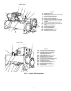
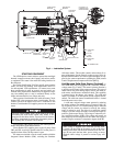
CHILLER FAMILIARIZATION
(Fig. 1 and 2)
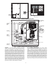
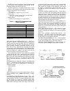
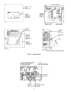
Chiller Information Nameplate —
The information
nameplate is located on the right side of the chiller control
panel.
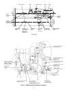
System Components —
The components include the
cooler and condenser heat exchangers in separate vessels,
motor-compressor, lubrication package, control panel, and mo-
tor starter. All connections from pressure vessels have external
threads to enable each component to be pressure tested with a
threaded pipe cap during factory assembly.
Cooler —
This vessel (also known as the evaporator) is lo-
cated underneath the compressor. The cooler is maintained at
lower temperature/pressure so evaporating refrigerant can re-
move heat from water flowing through its internal tubes.
Condenser —
The condenser operates at a higher
temperature/pressure than the cooler and has water flowing
through its internal tubes in order to remove heat from the
refrigerant.
Motor-Compressor —
This component maintains sys-
tem temperature and pressure differences and moves the heat-
carrying refrigerant from the cooler to the condenser.
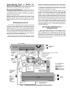
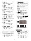
Control Panel —
The control panel is the user interface
for controlling the chiller. It regulates the chiller’s capacity as
required to maintain proper leaving chilled water temperature.
The control panel:
• registers cooler, condenser, and lubricating system
pressures
• shows chiller operating condition and alarm shutdown
conditions
• records the total chiller operating hours
• sequences chiller start, stop, and recycle under micropro-
cessor control
• displays status of motor starter
• provides access to other CCN (Carrier Comfort Net-
work) devices and energy management systems
• Languages pre-installed at factory include: English, Chi-
nese, Japanese, and Korean (ICVC only).
• International language translator (ILT) is available for
conversion of extended ASCII characters (ICVC only).
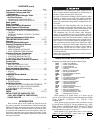
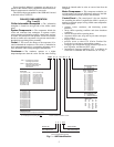
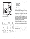
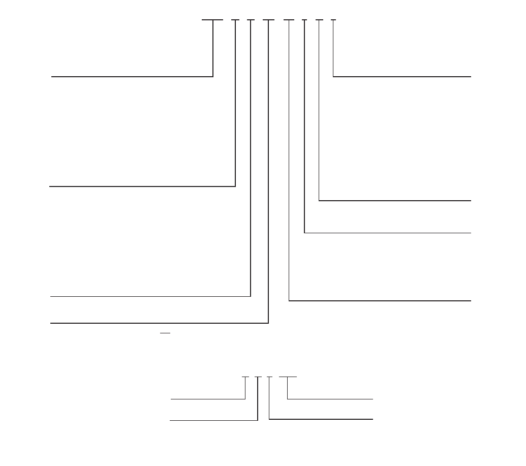
19XRV 52 51 473 DG H 64 –
19XR- — High Efficiency Hermetic
Centrifugal Liquid Chiller
19XRV — High Efficiency Hermetic
Centrifugal Liquid Chiller with
Variable Frequency Drive
Unit-Mounted
Condenser Size
10-12 (Frame 1 XR)
15-17 (Frame 1 XR)
20-22 (Frame 2 XR)
30-32 (Frame 3 XR)
35-37 (Frame 3 XR)
40-42 (Frame 4 XR)
45-47 (Frame 4 XR)
50-52 (Frame 5 XR)
55-57 (Frame 5 XR)
60-62 (Frame 6 XR)
65-67 (Frame 6 XR)
70-72 (Frame 7 XR)
75-77 (Frame 7 XR)
80-82 (Frame 8 XR)
85-87 (Frame 8 XR)
Special Order Indicator
– — Standard
S — Special Order
Motor Voltage Code
Code Volts-Phase-Hertz
60 — 200-3-60
61 — 230-3-60
62 — 380-3-60
63 — 416-3-60
64 — 460-3-60
65 — 575-3-60
66 — 2400-3-60
67 — 3300-3-60
68 — 4160-3-60
69 — 6900-3-60
50 — 230-3-50
51 — 346-3-50
52 — 400-3-50
53 — 3000-3-50
54 — 3300-3-50
55 — 6300-3-50
Compressor Code
(First Digit Indicates Compressor Frame Size)*
Motor Efficiency Code
H — High Efficiency
S — Standard Efficiency
Motor Code
BD CD DB EH
BE CE DC EJ
BF CL DD EK
BG CM DE EL
BH CN DF EM
CP DG EN
CQ DH EP
DJ
27 99 Q 59843
Week of Year
Year of Manufacture
Unique Number
Place of Manufacture
MODEL NUMBER NOMENCLATURE
SERIAL NUMBER BREAKDOWN
Cooler Size
10-12 (Frame 1 XR)
15-17 (Frame 1 XR)
20-22 (Frame 2 XR)
30-32 (Frame 3 XR)
35-37 (Frame 3 XR)
40-42 (Frame 4 XR)
45-47 (Frame 4 XR)
50-52 (Frame 5 XR)
5A (Frame 5 XR)
5B (Frame 5 XR)
5C (Frame 5 XR)
55-57 (Frame 5 XR)
5F (Frame 5 XR)
5G (Frame 5 XR)
5H (Frame 5 XR)
60-62 (Frame 6 XR)
65-67 (Frame 6 XR)
70-72 (Frame 7 XR)
75-77 (Frame 7 XR)
80-82 (Frame 8 XR)
85-87 (Frame 8 XR)
*Second digit will be a letter (example 4G3)
on units equipped with split ring diffuser.
Fig. 1 — 19XR Identification