


22
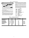
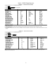
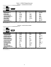
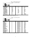
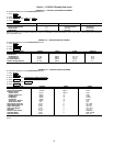
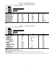
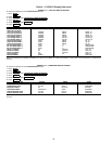
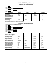
Table 2 — CVC/ICVC Display Data
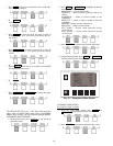
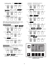
1. Only 12 lines of information appear on the chiller display screen
at any one time. Press the or softkey to
highlight a point or to view items below or above the current
screen. Press the softkey twice to page forward; press
the softkey twice to page back.
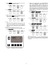
2. To access the information shown in Examples 10 through 22,
enter your 4-digit password after pressing the soft-
key. If no softkeys are pressed for 15 minutes, the CVC/ICVC
automatically logs off (to prevent unrestricted access to PIC II
controls) and reverts to the default screen. If this happens, you
must re-enter your password to access the tables shown in
Examples 10 through 22.
3. Terms in the Description column of these tables are listed as they
appear on the chiller display screen.
4. The CVC/ICVC may be configured in English or Metric (SI) units
using the CVC/ICVC CONFIGURATION screen. See the Service
Operation section, page 45, for instructions on making this
change.
5. The items in the Reference Point Name column do not appear on
the chiller display screen. They are data or variable names used
in CCN or Building Supervisor (BS) software. They are listed in
these tables as a convenience to the operator if it is necessary to
cross reference CCN/BS documentation or use CCN/BS pro-
grams. For more information, see the 19XR CCN literature.
6. Reference Point Names shown in these tables in all capital let-
ters can be read by CCN and BS software. Of these capitalized
names, those preceded by a dagger can also be changed (that
is, written to) by the CCN, BS, and the CVC/ICVC. Capitalized
Reference Point Names preceded by two asterisks can be
changed only from the CVC/ICVC. Reference Point Names in
lower case type can be viewed by CCN or BS only by viewing the
whole table.
7. Alarms and Alerts: An asterisk in the far right field of a CVC/
ICVC status screen indicates that the chiller is in an alarm state;
an exclamation point in the far right field of the CVC/ICVC screen
indicates an alert state. The asterisk (or exclamation point) indi-
cates that the value on that line has exceeded (or is approach-
ing) a limit. For more information on alarms and alerts, see the
Alarms and Alerts section, page 15.
LEGEND
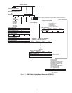
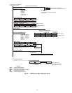
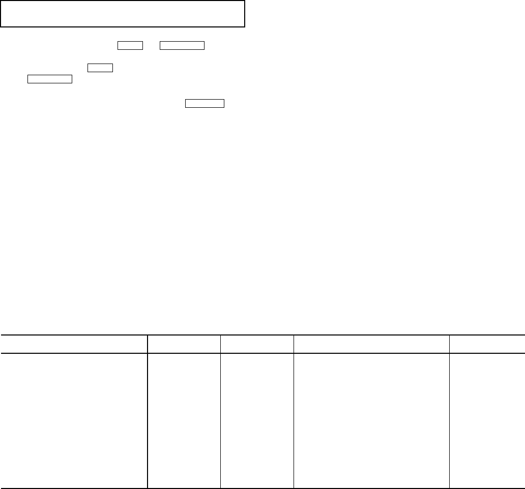
EXAMPLE 1 — CHILLER DISPLAY DEFAULT SCREEN
The following data is displayed in the Default screen.
NOTE: The last three entries are used to indicate operating mode to the PIC II. These values may be forced by the CVC/ICVC only.
IMPORTANT: The following notes apply to all Table 2
examples.
NEXT PREVIOUS
NEXT
PREVIOUS
SERVICE
CCN — Carrier Comfort Network
CHW — Chilled Water
CHWR — Chilled Water Return
CHWS — Chilled Water Supply
CVC — Chiller Visual Controller
CT — Current Transformer
ECW — Entering Chilled Water
HGBP — Hot Gas Bypass
ICVC — International Chiller Visual Controller
ISM — Integrated Starter Module
LCW — Leaving Chilled Water
LRA — Locked Rotor Amps
mA — Milliamps
P — Pressure
PIC II — Product Integrated Controls II
SS — Solid State
T — Temperature
VFD — Variable Frequency Drive
WSM — Water System Manager
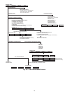
DESCRIPTION STATUS UNITS
REFERENCE POINT NAME
(ALARM HISTORY)
DISPLAY
(PRIMARY MESSAGE)
(SECONDARY MESSAGE)
(DATE AND TIME)
Compressor Ontime 0-500000.0 HOURS C_HRS
Entering Chilled Water –40-245 DEG F ECW CHW IN
Leaving Chilled Water –40-245 DEG F LCW CHW OUT
Evaporator Temperature –40-245 DEG F ERT EVAP REF
Entering Condenser Water –40-245 DEG F ECDW CDW IN
Leaving Condenser Water –40-245 DEG F LCDW CDW OUT
Condenser Temperature –40-245 DEG F CRT COND REF
Oil Pressure 0-420 PSI OILPD OILPRESS
Oil Sump Temp 40-245 DEG F OILT OIL TEMP
Average Line Current 0-999 % AMPS_% AMPS%
0-1 CCN
0-1 LOCAL
0-1 RESET