


64
CHILLER EQUALIZATION WITH PUMPOUT UNIT —
The following steps describe how to equalize refrigerant pres-
sure on an isolated 19XR chiller using the pumpout unit.
1. Access the terminate lockout function on the CONTROL
TEST screen.
2.
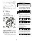
3. Open valve 4 on the pumpout unit and open valves 1a and
1b on the chiller cooler and condenser, Fig. 29 and 30.
Slowly open valve 2 on the pumpout unit to equalize the
pressure. This process takes approximately 15 minutes.
4. Once the pressures have equalized, the discharge isola-
tion valve, cooler isolation valve, optional hot gas bypass
isolation valve, and the refrigerant isolation valve can be
opened. Close valves 1a and 1b, and all pumpout unit
valves.
The full refrigerant charge on the 19XR will vary with chill-
er components and design conditions, as indicated on the job
data specifications. An approximate charge may be determined
by adding the condenser charge to the cooler charge as listed in
Table 10.
Use the CONTROL TEST terminate lockout function to
monitor conditions and start the pumps.
If the chiller has been shipped with a holding charge
, the
refrigerant is added through the pumpout charging connection
(Fig. 29 and 30, valve 1b). First evacuate the nitrogen holding
charge from the chiller vessels. Charge the refrigerant as a gas
until the system pressure exceeds 35 psig (141 kPa) for
HFC-134a. After the chiller is beyond this pressure the refrig-
erant should be charged as a liquid until all the recommended
refrigerant charge has been added. The charging valve (Fig. 29
and 30, valve 7) can be used to charge liquid to the cooler if the
cooler isolation valve (11) is present and is closed. Do not
charge liquid through the linear float to the condenser.
TRIMMING REFRIGERANT CHARGE — The 19XR is
shipped with the correct charge for the design duty of the chill-
er. Trimming the charge can best be accomplished when the
design load is available. To trim the charge, check the tempera-
ture difference between the leaving chilled water temperature
and cooler refrigerant temperature at full load design condi-
tions. If necessary, add or remove refrigerant to bring the
temperature difference to design conditions or minimum
differential.
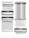
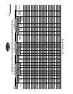
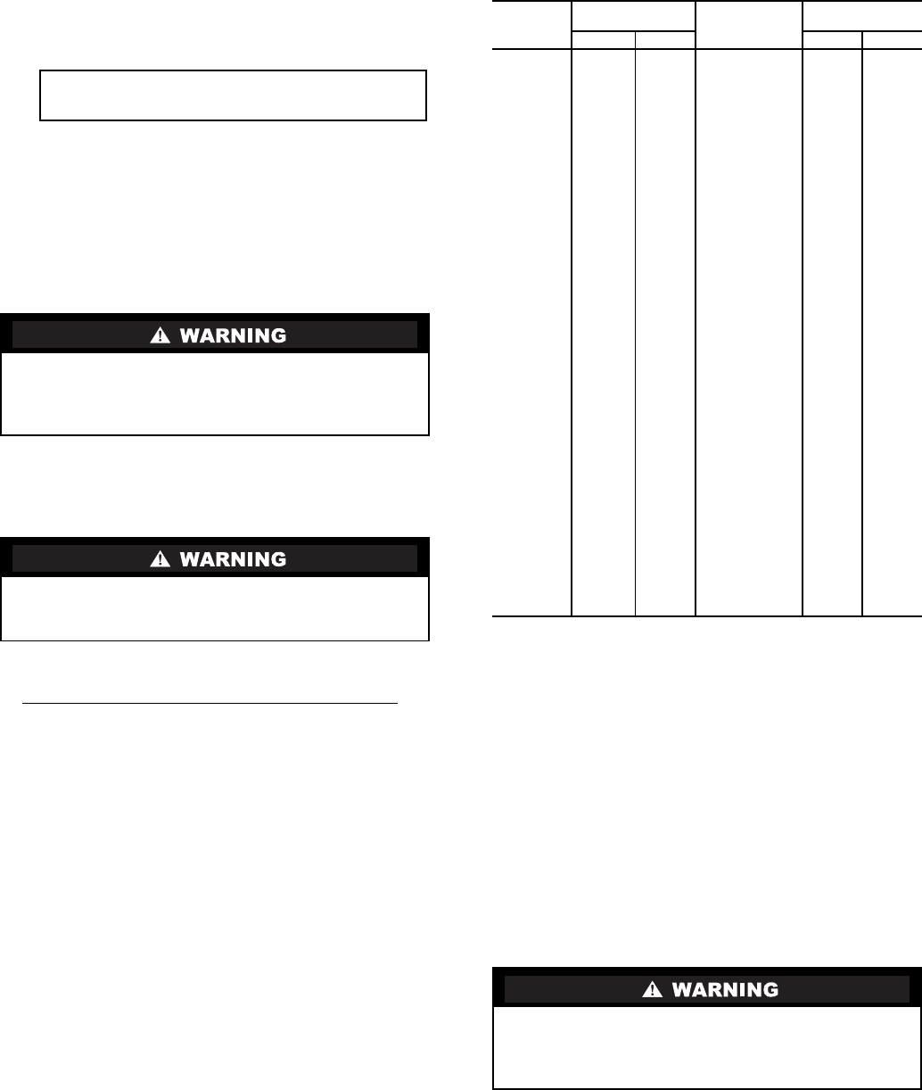
Table 10 lists the 19XR chiller refrigerant charges for each
cooler and condenser code. Total refrigerant charge is the sum
of the cooler and condenser charge.
Table 10 — Refrigerant (HFC-134a) Charge
INITIAL START-UP
Preparation —
Before starting the chiller, verify:
1. Power is on to the main starter, oil pump relay, tower fan
starter, oil heater relay, and the chiller control panel.
2. Cooling tower water is at proper level and at-or-below
design entering temperature.
3. Chiller is charged with refrigerant and all refrigerant and
oil valves are in their proper operating positions.
4. Oil is at the proper level in the reservoir sight glasses.
5. Oil reservoir temperature is above 140 F (60 C) or above
refrigerant temperature plus 50° F (28° C).
6. Valves in the evaporator and condenser water circuits are
open.
NOTE: If the pumps are not automatic, ensure water is
circulating properly.
7. Access the CONTROL TEST screen. Scroll down on the
TERMINATE LOCKOUT option. Press the SELECT (to
enable the chiller to start) and answer YES to reset unit to
operating mode. The chiller is locked out at the factory in
order to prevent accidental start-up.
Whenever turning the discharge isolation valve, be sure to
reattach the valve locking device. This prevents the valve
from opening or closing during service work or during
chiller operation.
Always operate the condenser and chilled water pumps
whenever charging, transferring, or removing refrigerant
from the chiller.
IMPORTANT: Turn on the chilled water and con-
denser water pumps to prevent freezing.
COOLER
CODE
REFRIGERANT
CHARGE
CONDENSER
CODE
REFRIGERANT
CHARGE
lb kg lb kg
10 290 132 10 200 91
11 310 141 11 200 91
12 330 150 12 200 91
15 320 145 15 250 113
16 340 154 16 250 113
17 370 168 17 250 113
20 345 157 20 225 102
21 385 175 21 225 102
22 435 197 22 225 102
30 350 159 30 260 118
31 420 190 31 260 118
32 490 222 32 260 118
35 400 181 35 310 141
36 480 218 36 310 141
37 550 250 37 310 141
40 560 254 40 280 127
41 630 286 41 280 127
42 690 313 42 280 127
45 640 290 45 330 150
46 720 327 46 330 150
47 790 358 47 330 150
50 750 340 50 400 181
51 840 381 51 400 181
52 900 408 52 400 181
55 870 395 55 490 222
56 940 426 56 490 222
57 980 445 57 490 222
60 940 426 60 420 190
61 980 445 61 420 190
62 1020 463 62 420 190
65 1020 463 65 510 231
66 1060 481 66 510 231
67 1090 494 67 510 231
70 1220 553 70 780 354
71 1340 608 71 780 354
72 1440 653 72 780 354
75 1365 619 75 925 420
76 1505 683 76 925 420
77 1625 737 77 925 420
80 1500 680 80 720 327
81 1620 735 81 720 327
82 1730 785 82 720 327
85 1690 766 85 860 390
86 1820 825 86 860 390
87 1940 880 87 860 390
Do not permit water or brine that is warmer than 110 F
(43 C) to flow through the cooler or condenser. Refrigerant
overpressure may discharge through the relief valves and
result in the loss of refrigerant charge.