


7
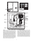
Factory-Mounted Starter or Variable Fre-
quency Drive (Optional) —
The starter allows for the
proper start and disconnect of electrical energy for the com-
pressor-motor, oil pump, oil heater, and control panel.
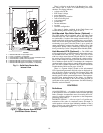
Storage Vessel (Optional) —
There are 2 sizes of
storage vessels available. The vessels have double relief valves,
a magnetically-coupled dial-type refrigerant level gage, a
one-inch FPT drain valve, and a
1
/
2
-in. male flare vapor con-
nection for the pumpout unit.
NOTE: If a storage vessel is not used at the jobsite, factory-
installed isolation valves on the chiller may be used to isolate
the chiller charge in either the cooler or condenser. An optional
pumpout system is used to transfer refrigerant from vessel to
vessel.
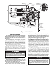
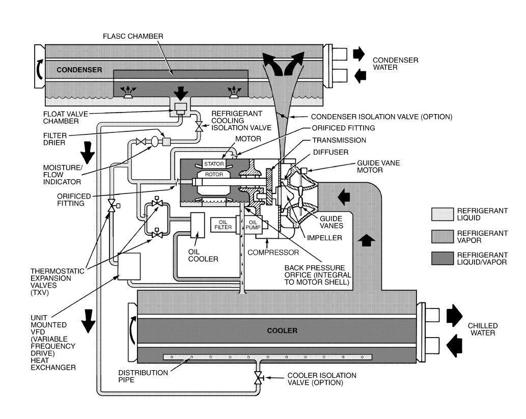
REFRIGERATION CYCLE
The compressor continuously draws refrigerant vapor from
the cooler at a rate set by the amount of guide vane opening or
compressor speed (19XRV only). As the compressor suction
reduces the pressure in the cooler, the remaining refrigerant
boils at a fairly low temperature (typically 38 to 42 F [3 to
6 C]). The energy required for boiling is obtained from the wa-
ter flowing through the cooler tubes. With heat energy re-
moved, the water becomes cold enough to use in an air condi-
tioning circuit or for process liquid cooling.
After taking heat from the water, the refrigerant vapor is
compressed. Compression adds still more heat energy, and the
refrigerant is quite warm (typically 98 to 102 F [37 to 40 C])
when it is discharged from the compressor into the condenser.
Relatively cool (typically 65 to 90 F [18 to 32 C]) water
flowing into the condenser tubes removes heat from the refrig-
erant and the vapor condenses to liquid.
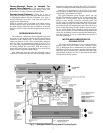
The liquid refrigerant passes through orifices into the
FLASC (Flash Subcooler) chamber (Fig. 3). Since the FLASC
chamber is at a lower pressure, part of the liquid refrigerant
flashes to vapor, thereby cooling the remaining liquid. The
FLASC vapor is recondensed on the tubes which are cooled by
entering condenser water. The liquid drains into a float cham-
ber between the FLASC chamber and cooler. Here a float valve
forms a liquid seal to keep FLASC chamber vapor from enter-
ing the cooler. When liquid refrigerant passes through the
valve, some of it flashes to vapor in the reduced pressure on the
cooler side. In flashing, it removes heat from the remaining liq-
uid. The refrigerant is now at a temperature and pressure at
which the cycle began.
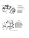
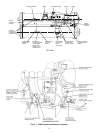
MOTOR AND LUBRICATING OIL
COOLING CYCLE
The motor and the lubricating oil are cooled by liquid re-
frigerant taken from the bottom of the condenser vessel
(Fig. 3). Refrigerant flow is maintained by the pressure differ-
ential that exists due to compressor operation. After the refrig-
erant flows past an isolation valve, an in-line filter, and a sight
glass/moisture indicator, the flow is split between the motor
cooling and oil cooling systems.
Fig. 3 — Refrigerant Motor Cooling and Oil Cooling Cycles