


36
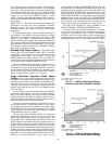
Ramp Loading —
The ramp loading control slows down
the rate at which the compressor loads up. This control can pre-
vent the compressor from loading up during the short period of
time when the chiller is started and the chilled water loop has to
be brought down to CONTROL POINT. This helps reduce
electrical demand charges by slowly bringing the chilled water
to CONTROL POINT. The total power draw during this period
remains almost unchanged.
There are two methods of ramp loading with the PIC II.
Ramp loading can be based on chilled water temperature or on
motor load. Either method is selected from the RAMP__DEM
screen.
1. Temperature ramp loading
(TEMP PULLDOWN DEG/
MIN) limits the degrees per minute rate at which either
leaving chilled water or entering chilled water tempera-
ture decreases. This rate is configured by the operator on
the TEMP_CTL screen. The lowest temperature ramp
rate will also be used if chiller power has been off for
3 hours or more (even if the motor ramp load is selected
as the ramp loading method).
2. Motor load ramp loading
(LOAD PULLDOWN) limits
the degrees per minute rate at which the compressor mo-
tor current or compressor motor load increases. The
LOAD PULLDOWN rate is configured by the operator
on the RAMP_DEM screen in amps or kilowatts. The
point name is MOTOR LOAD RAMP%/MIN.
If kilowatts is selected for the DEMAND LIMIT SOURCE,
the MOTOR RATED KILOWATTS must be entered (informa-
tion found on the chiller Requisition form).
The TEMP PULLDOWN DEG/MIN may be viewed or
modified on the TEMP_CTL screen which is accessed from
the EQUIPMENT SERVICE screen. PULLDOWN RAMP
TYPE, DEMAND LIMIT SOURCE, and MOTOR LOAD
RAMP %/MIN may be viewed or modified on the
RAMP_DEM screen.
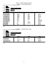
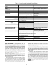
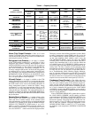
Capacity Override (Table 4) —
Capacity overrides can
prevent some safety shutdowns caused by exceeding the motor
amperage limit, refrigerant low temperature safety limit, motor
high temperature safety limit, and condenser high pressure
limit. In all cases there are 2 stages of compressor vane control.
1. The vanes are prevented from opening further, and the
status line on the CVC/ICVC indicates the reason for the
override.
2. The vanes are closed until the condition decreases to be-
low the first step set point. Then the vanes are released to
normal capacity control.
Whenever the motor current demand limit set point
(ACTIVE DEMAND LIMIT) is reached, it activates a capacity
override, again, with a 2-step process. Exceeding 110% of the
rated load amps for more than 30 seconds will initiate a safety
shutdown.
The compressor high lift (surge prevention) set point will
cause a capacity override as well. When the surge prevention
set point is reached, the controller normally will only prevent
the guide vanes from opening. If so equipped, the hot gas by-
pass valve will open instead of holding the vanes. See the
Surge Prevention Algorithm section, page 39.
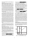
High Discharge Temperature Control —
If the
discharge temperature increases above 160 F (71.1 C), the
guide vanes are proportionally opened to increase gas flow
through the compressor. If the leaving chilled water tempera-
ture is then brought 5° F (2.8° C) below the control set point
temperature, the PIC II will bring the chiller into the recycle
mode.
Oil Sump Temperature Control —
The oil sump
temperature control is regulated by the PIC II, which uses the
oil heater relay when the chiller is shut down.
As part of the pre-start checks executed by the controls, the
oil sump temperature (OIL SUMP TEMP) is compared to the
cooler refrigerant temperature (EVAPORATOR REFRIG
TEMP). If the difference between these 2 temperatures is 50 F
(27.8 C) or less, the start-up will be delayed until the oil tem-
perature is 50 F (27.8 C) or more. Once this temperature is con-
firmed, the start-up continues.
The oil heater relay is energized whenever the chiller com-
pressor is off and the oil sump temperature is less than 140 F
(60.0 C) or the oil sump temperature is less than the cooler re-
frigerant temperature plus 53° F (11.7° C). The oil heater is
turned off when the oil sump temperature is either
• more than 152 F (66.7 C), or
• more than 142 F (61.1 C) and more than the cooler
refrigerant temperature plus 55° F (12.8° C).
The oil heater is always off during start-up or when the
compressor is running.
The oil pump is also energized during the time the oil is be-
ing heated (for 60 seconds at the end of every 30 minutes).
Oil Cooler —
The oil must be cooled when the compres-
sor is running. This is accomplished through a small, plate-type
heat exchanger (also called the oil cooler) located behind the
oil pump. The heat exchanger uses liquid condenser refrigerant
as the cooling liquid. Refrigerant thermostatic expansion
valves (TXVs) regulate refrigerant flow to control the oil tem-
perature entering the bearings. The bulbs for the expansion
valves are strapped to the oil supply line leaving the heat ex-
changer, and the valves are set to maintain 110 F (43 C).
NOTE: The TXVs are not adjustable. The oil sump tempera-
ture may be at a lower temperature during compressor
operations.
Remote Start/Stop Controls —
A remote device, such
as a timeclock that uses a set of contacts, may be used to start
and stop the chiller. However, the device should not be pro-
grammed to start and stop the chiller in excess of 2 or 3 times
every 12 hours. If more than 8 starts in 12 hours (the STARTS
IN 12 HOURS parameter on the MAINSTAT screen) occur, an
excessive starts alarm displays, preventing the chiller from
starting. The operator must press the softkey on the
CVC/ICVC to override the starts counter and start the chiller.
If the chiller records 12 starts (excluding recycle starts) in a
sliding 12-hour period, it can be restarted only by pressing the
softkey followed by the or softkey.
This ensures that, if the automatic system is malfunctioning,
the chiller will not repeatedly cycle on and off. If the automatic
restart after a power failure option (AUTO RESTART OPTION
on the OPTIONS screen) is not activated when a power failure
occurs, and if the remote contact is closed, the chiller will indi-
cate an alarm because of the loss of voltage.
The contacts for remote start are wired into the starter at ter-
minal strip J2, terminals 5 and 6 on the ISM. See the certified
drawings for further details on contact ratings. The contacts
must have 24 vac dry contact rating.
Spare Safety Inputs —
Normally closed (NC) discrete
inputs for additional field-supplied safeties may be wired to the
spare protective limits input channel in place of the factory-
installed jumper. (Wire multiple inputs in series.) The opening
of any contact will result in a safety shutdown and a display on
the CVC/ICVC. Refer to the certified drawings for safety con-
tact ratings.
Analog temperature sensors may also be added to the mod-
ule (SPARE TEMP #1 and #2). The analog temperature sen-
sors may be configured to cause an alert or alarm on the CCN
network. The alert will not shut the chiller down. Configuring
for alarm state will cause the chiller to shut down.
RESET
RESET LOCAL CCN